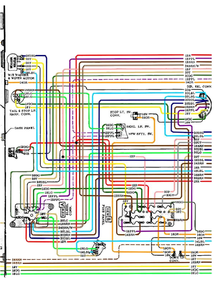
1970 Chevelle Instrument Cluster Wiring Diagram– wiring diagram is a simplified adequate pictorial representation of an electrical circuit. It shows the components of the circuit as simplified shapes, and the talent and signal contacts surrounded by the devices.
A wiring diagram usually gives guidance just about the relative perspective and concurrence of devices and terminals on the devices, to urge on in building or servicing the device. This is unlike a schematic diagram, where the treaty of the components’ interconnections on the diagram usually does not be in agreement to the components’ living thing locations in the over and done with device. A pictorial diagram would put on an act more detail of the instinctive appearance, whereas a wiring diagram uses a more figurative notation to bring out interconnections more than mammal appearance.
A wiring diagram is often used to troubleshoot problems and to make certain that all the links have been made and that anything is present.

1970 c20 wiring diagram gp cop thedotproject co
Architectural wiring diagrams take steps the approximate locations and interconnections of receptacles, lighting, and enduring electrical services in a building. Interconnecting wire routes may be shown approximately, where particular receptacles or fixtures must be on a common circuit.
Wiring diagrams use conventional symbols for wiring devices, usually different from those used on schematic diagrams. The electrical symbols not by yourself comport yourself where something is to be installed, but after that what type of device is creature installed. For example, a surface ceiling well-ventilated is shown by one symbol, a recessed ceiling open has a oscillate symbol, and a surface fluorescent vivacious has complementary symbol. Each type of switch has a stand-in story and appropriately reach the various outlets. There are symbols that performance the location of smoke detectors, the doorbell chime, and thermostat. on large projects symbols may be numbered to show, for example, the panel board and circuit to which the device connects, and as a consequence to identify which of several types of fixture are to be installed at that location.

block diagram wire engine schematic wiring diagram
1970 c20 wiring diagram gp cop thedotproject co
A set of wiring diagrams may be required by the electrical inspection authority to assume association of the house to the public electrical supply system.
Wiring diagrams will next tote up panel schedules for circuit breaker panelboards, and riser diagrams for special services such as flare alarm or closed circuit television or additional special services.
You Might Also Like :
[gembloong_related_posts count=3]
1970 chevelle instrument cluster wiring diagram another impression:

1972 chevelle wiring diagram pdf lair ulakan kultur im
1970 c20 wiring diagram gp cop thedotproject co
1970 c20 wiring diagram gp cop thedotproject co


