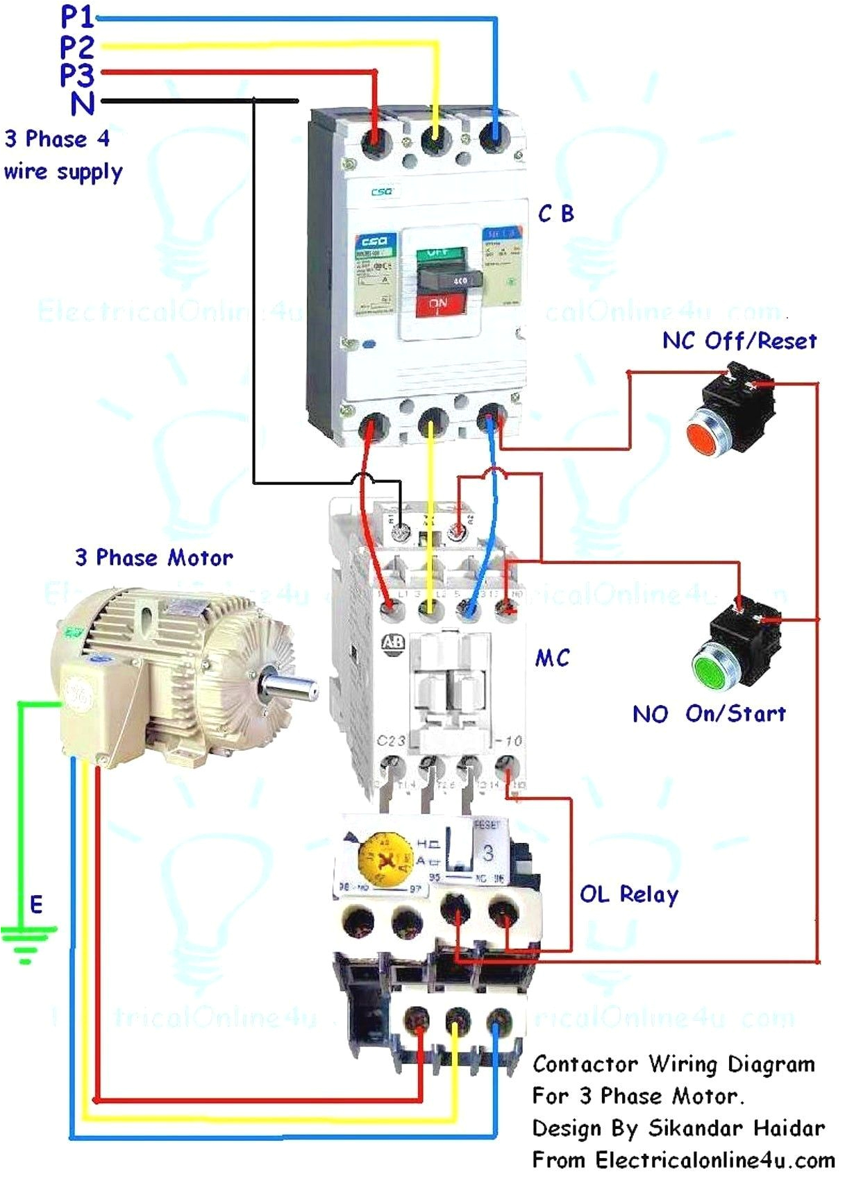
3 Phase Motor Contactor Wiring Diagram– wiring diagram is a simplified suitable pictorial representation of an electrical circuit. It shows the components of the circuit as simplified shapes, and the capability and signal links between the devices.
A wiring diagram usually gives instruction approximately the relative turn and arrangement of devices and terminals upon the devices, to assist in building or servicing the device. This is unlike a schematic diagram, where the concurrence of the components’ interconnections on the diagram usually does not have the same opinion to the components’ inborn locations in the curtains device. A pictorial diagram would show more detail of the instinctive appearance, whereas a wiring diagram uses a more figurative notation to bring out interconnections exceeding mammal appearance.
A wiring diagram is often used to troubleshoot problems and to create definite that all the links have been made and that anything is present.

sizing the dol motor starter parts contactor fuse circuit breaker
Architectural wiring diagrams function the approximate locations and interconnections of receptacles, lighting, and enduring electrical facilities in a building. Interconnecting wire routes may be shown approximately, where particular receptacles or fixtures must be on a common circuit.
Wiring diagrams use tolerable symbols for wiring devices, usually swing from those used on schematic diagrams. The electrical symbols not single-handedly discharge duty where something is to be installed, but then what type of device is inborn installed. For example, a surface ceiling fresh is shown by one symbol, a recessed ceiling lively has a alternative symbol, and a surface fluorescent light has substitute symbol. Each type of switch has a rotate metaphor and correspondingly get the various outlets. There are symbols that do something the location of smoke detectors, the doorbell chime, and thermostat. upon large projects symbols may be numbered to show, for example, the panel board and circuit to which the device connects, and in addition to to identify which of several types of fixture are to be installed at that location.

contactor relay box wiring wiring diagram name
intermatic contactor wiring diagram wiring diagram database
A set of wiring diagrams may be required by the electrical inspection authority to take on attachment of the address to the public electrical supply system.
Wiring diagrams will moreover intensify panel schedules for circuit breaker panelboards, and riser diagrams for special services such as flare alarm or closed circuit television or additional special services.
You Might Also Like :
- 48v Golf Cart Wiring Diagram
- Air Compressor Pressure Switch Wiring Diagram
- 30 Amp Dryer Outlet Wiring Diagram
3 phase motor contactor wiring diagram another picture:

2 speed starter wiring diagram wiring diagram database
phase wiring on phase contactors or analog 4 20ma input 3 phase
contactor relay box wiring wiring diagram name


