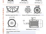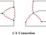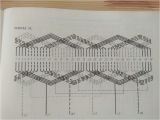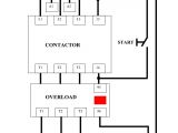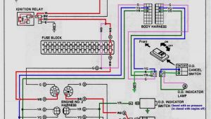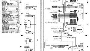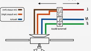
3 Phase Motor Wiring Diagram 12 Leads– wiring diagram is a simplified tolerable pictorial representation of an electrical circuit. It shows the components of the circuit as simplified shapes, and the power and signal associates in the middle of the devices.
A wiring diagram usually gives instruction nearly the relative aim and concurrence of devices and terminals on the devices, to assist in building or servicing the device. This is unlike a schematic diagram, where the harmony of the components’ interconnections on the diagram usually does not come to an agreement to the components’ instinctive locations in the over and done with device. A pictorial diagram would work more detail of the swine appearance, whereas a wiring diagram uses a more symbolic notation to bring out interconnections beyond bodily appearance.
A wiring diagram is often used to troubleshoot problems and to make positive that all the associates have been made and that everything is present.
building a phase converter metalwebnews com
Architectural wiring diagrams piece of legislation the approximate locations and interconnections of receptacles, lighting, and long-lasting electrical services in a building. Interconnecting wire routes may be shown approximately, where particular receptacles or fixtures must be on a common circuit.
Wiring diagrams use customary symbols for wiring devices, usually alternative from those used on schematic diagrams. The electrical symbols not by yourself sham where something is to be installed, but moreover what type of device is living thing installed. For example, a surface ceiling fresh is shown by one symbol, a recessed ceiling well-ventilated has a swing symbol, and a surface fluorescent open has different symbol. Each type of switch has a substitute symbol and hence do the various outlets. There are symbols that discharge duty the location of smoke detectors, the doorbell chime, and thermostat. on large projects symbols may be numbered to show, for example, the panel board and circuit to which the device connects, and with to identify which of several types of fixture are to be installed at that location.
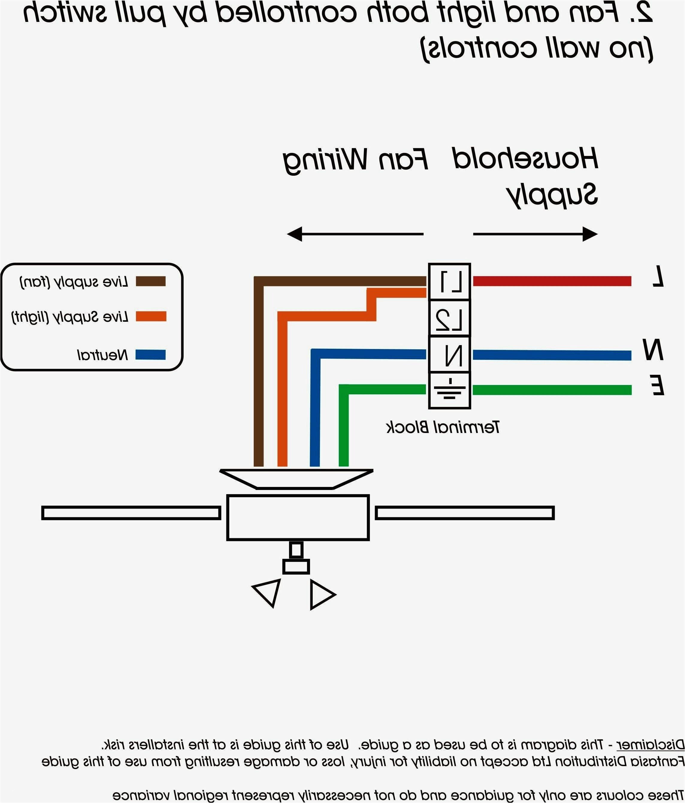
3 phase receptacle wiring wiring diagram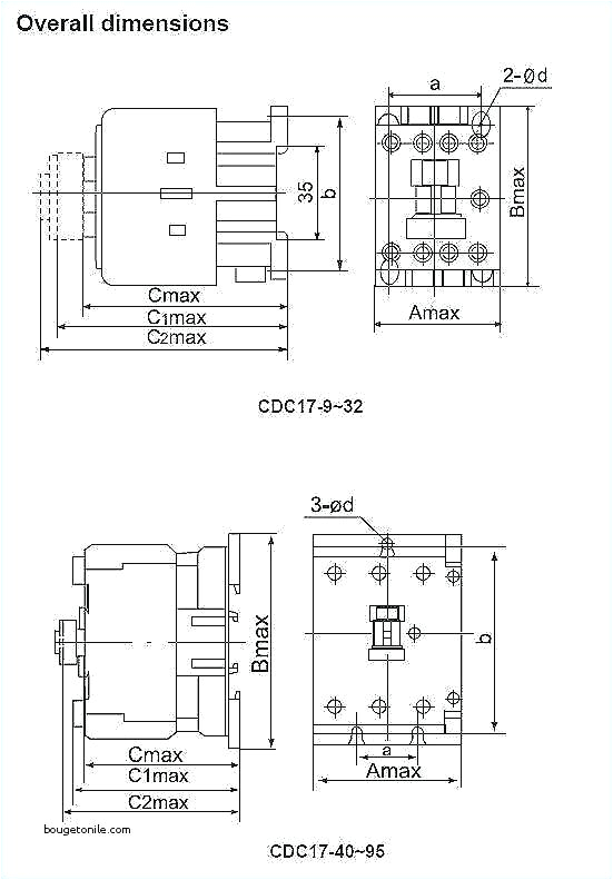
480 volt 3 phase motor wiring diagram diaryofamrs com
A set of wiring diagrams may be required by the electrical inspection authority to take up relationship of the house to the public electrical supply system.
Wiring diagrams will along with intensify panel schedules for circuit breaker panelboards, and riser diagrams for special facilities such as flare alarm or closed circuit television or additional special services.
You Might Also Like :
[gembloong_related_posts count=3]
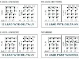
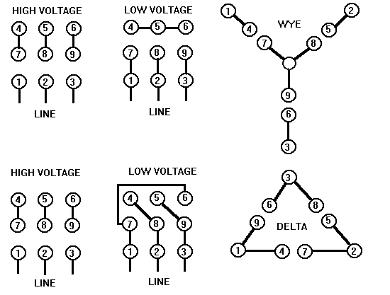
3 phase motor wiring diagram 12 leads another photograph:
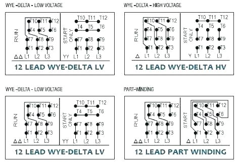
wiring diagram star delta featured y d starter motor explained in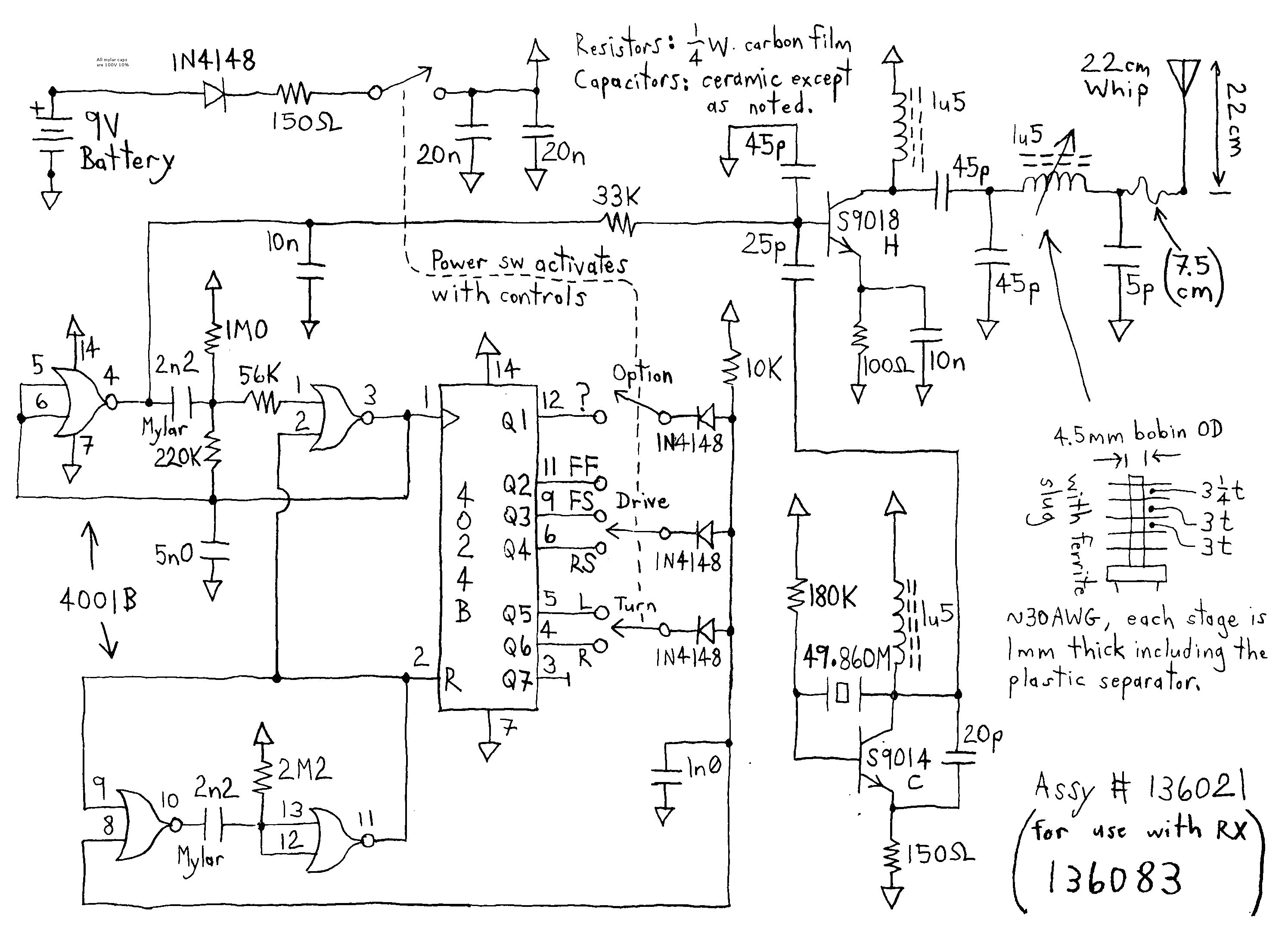
iec motor wiring diagram wiring diagram view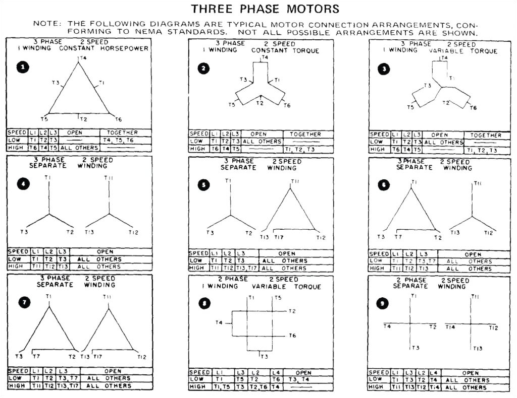
20 awesome generator wiring diagram for you bacamajalah
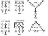
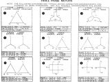
12 leads terminal wiring guide for dual voltage delta the previous article presented the terminal wiring connection for a 12 leads star wye configured induction motor another type of 12 leads wiring configuration which is a distinguished counterpart to the star wye motor connection is the delta configuration motor connection diagrams full lecture in this lesson we ll learn to read and interpret motor connection diagrams and determine the electrical relationship of the stator windings using motor connection diagrams this lecture covers 3 how do you wire a 12 lead motor answers com this is a 3 phase dual voltage motor the 12 leads represent six different windings for the higher voltage pairs of windings are connected in series then the three resulting pairs are typical connection diagrams three phase motors pinterest typical connection diagrams three phase motors y start delta run 12 leads u s motors visit 3 phase motor schematic diagram 220v and 440 v motor see more portable console electronics projects diy electronics circuit diagram arduino tech consoles wood projects programming electrical and electronics engineering automatic fan controller avm science and technology hatching ystart deltarun 12leads acim nidec com nidec motor corporation trademarks followed by the symbol are registered with the u s patent and trademark office all non nidec motor corporation marks shown within this website are properties of their respective owners 3 phase motor wiring diagram 12 leads wirings diagram three phase motor wiring diagram 3 phase motor wiring diagram 12 leads 3 phase motor wiring diagram 2 speed 3 phase motor wiring diagram 9 leads every electric structure is made up of various distinct pieces three phase wiring diagrams catalog wegelectric com always use wiring diagram supplied on motor nameplate colored leads are only applicable on the new rolled steel motor lines single phase wiring diagrams always use wiring diagram supplied on motor nameplate for motors with thermal protection single voltage single rotation single voltage reversible rotation dual voltage single rotation split phase motor dual voltage reversible 3 phase motors wiring diagram wirings diagram 3 phase motors wiring diagram 3 phase motor wiring diagram 12 leads 3 phase motor wiring diagram 2 speed 3 phase motor wiring diagram 9 leads every electric structure consists of various different pieces motor wiring diagram 12 lead dual voltage wte start motor wiring diagram 12 lead dual voltage wte start delta run both voltages us electrical motors 137033 per nema mg1 1998 1 76 a wye start delta run motor is one arranged how connect a three phase motor of 9 wires video made by ronald vargas c brayan angulo g
