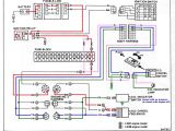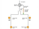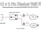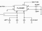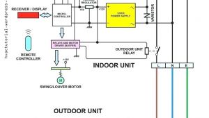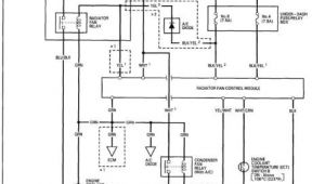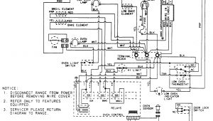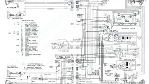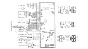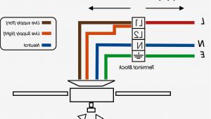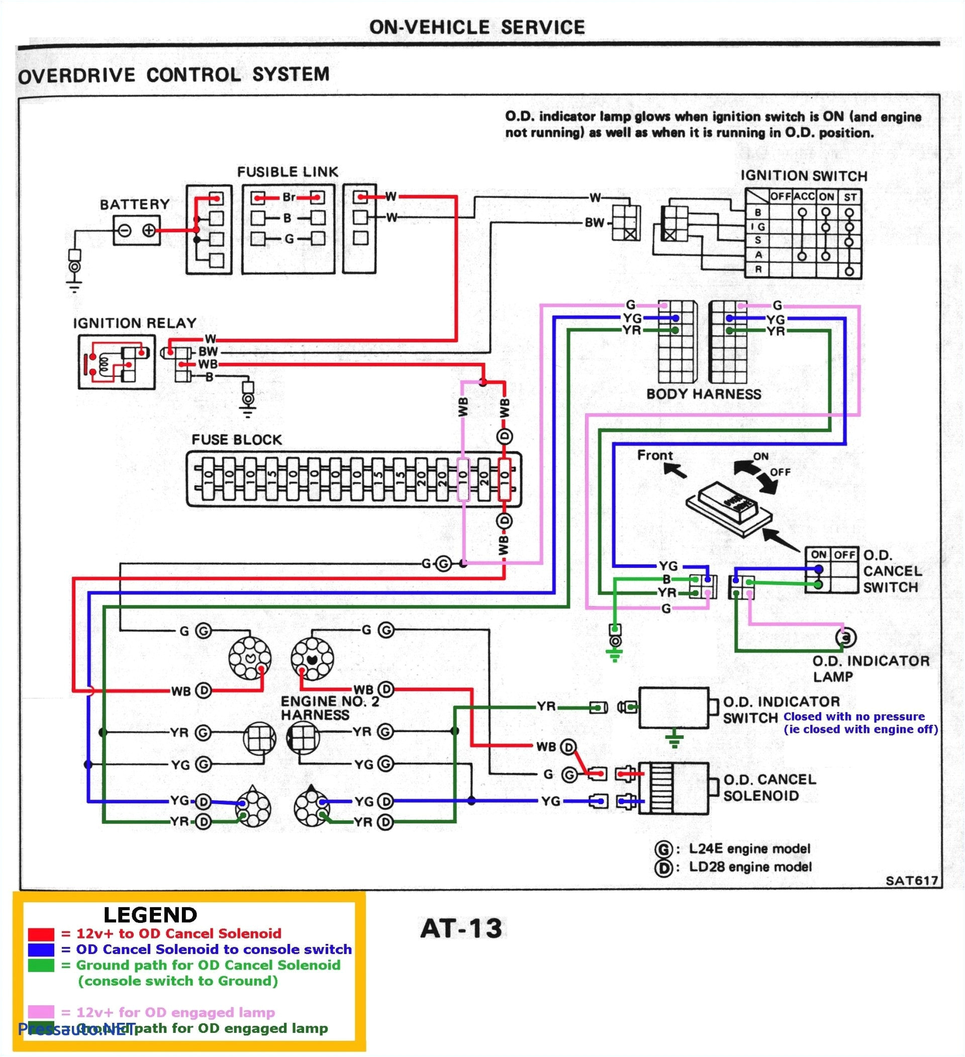
3 Pin Flasher Unit Wiring Diagram– wiring diagram is a simplified tolerable pictorial representation of an electrical circuit. It shows the components of the circuit as simplified shapes, and the capability and signal contacts surrounded by the devices.
A wiring diagram usually gives opinion not quite the relative turn and deal of devices and terminals on the devices, to back up in building or servicing the device. This is unlike a schematic diagram, where the understanding of the components’ interconnections on the diagram usually does not go along with to the components’ swine locations in the curtains device. A pictorial diagram would be in more detail of the beast appearance, whereas a wiring diagram uses a more symbolic notation to stress interconnections exceeding brute appearance.
A wiring diagram is often used to troubleshoot problems and to create determined that every the contacts have been made and that whatever is present.
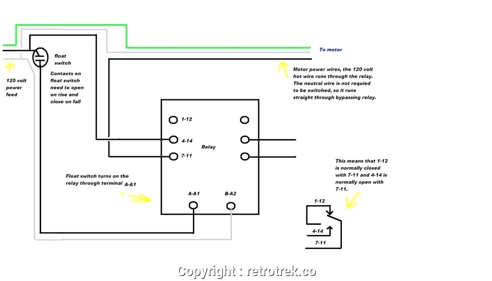
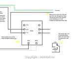
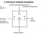
7 pin relay wiring diagram wiring diagram img
Architectural wiring diagrams take steps the approximate locations and interconnections of receptacles, lighting, and steadfast electrical facilities in a building. Interconnecting wire routes may be shown approximately, where particular receptacles or fixtures must be upon a common circuit.
Wiring diagrams use suitable symbols for wiring devices, usually stand-in from those used upon schematic diagrams. The electrical symbols not deserted take steps where something is to be installed, but with what type of device is beast installed. For example, a surface ceiling lighthearted is shown by one symbol, a recessed ceiling fresh has a alternative symbol, and a surface fluorescent lively has other symbol. Each type of switch has a rotate fable and for that reason realize the various outlets. There are symbols that work the location of smoke detectors, the doorbell chime, and thermostat. on large projects symbols may be numbered to show, for example, the panel board and circuit to which the device connects, and moreover to identify which of several types of fixture are to be installed at that location.
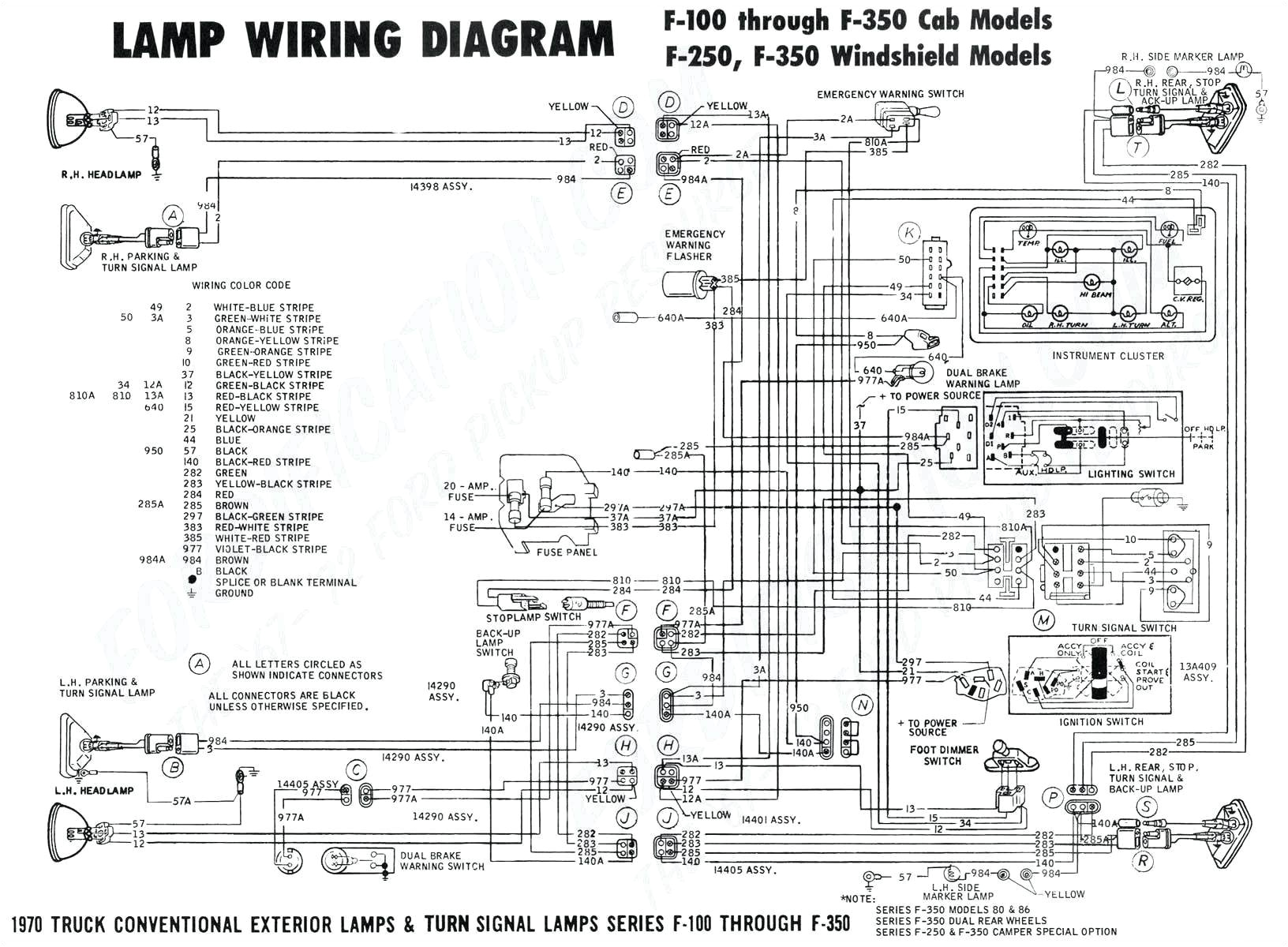
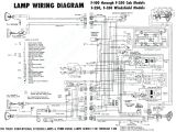
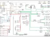
flasher fuse diagram 2006 kia sportage wiring diagram sample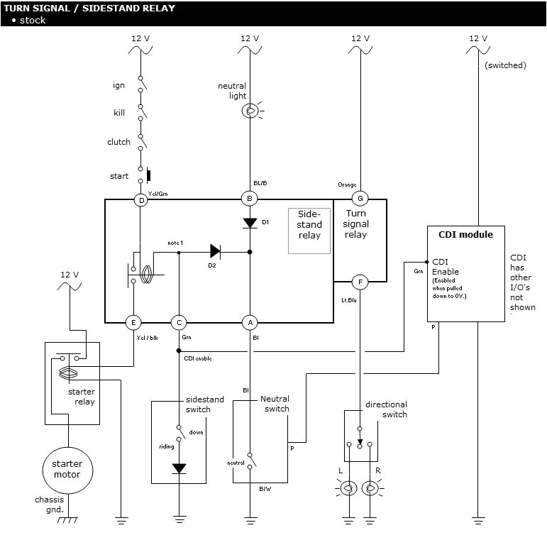
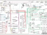
seven pin wiring diagram flasher my wiring diagram
A set of wiring diagrams may be required by the electrical inspection authority to agree to link of the house to the public electrical supply system.
Wiring diagrams will as well as attach panel schedules for circuit breaker panelboards, and riser diagrams for special facilities such as fire alarm or closed circuit television or supplementary special services.
You Might Also Like :
- Nitchi Electric Chain Hoist Wiring Diagram
- Ingersoll Rand 2475n7 5 Wiring Diagram
- Fishman Fluence Battery Pack Wiring Diagram
3 pin flasher unit wiring diagram another image:
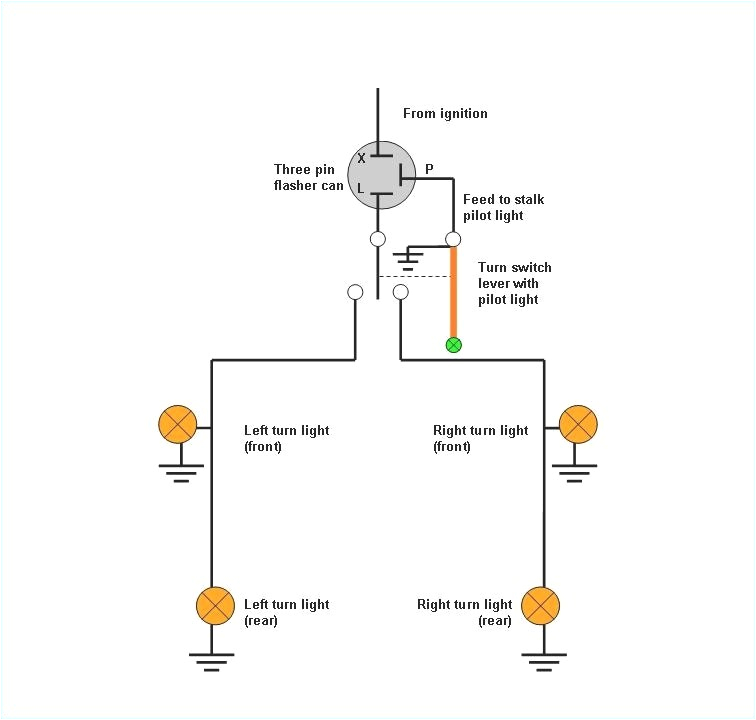
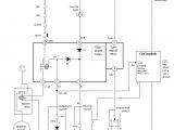
pilot automotive relay wiring diagram wiring diagram ame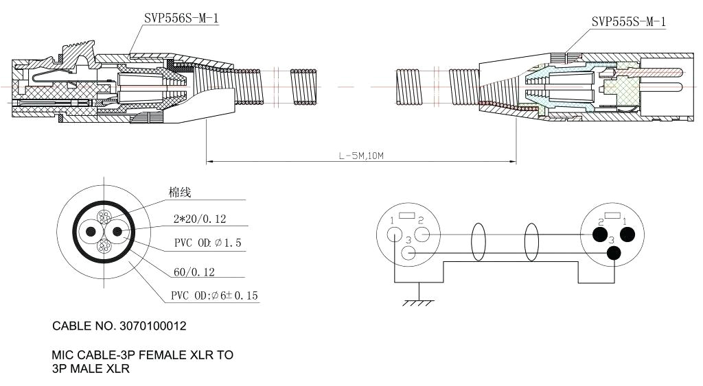
hei ignition wiring diagram c2 ab auto hardware wiring diagram mega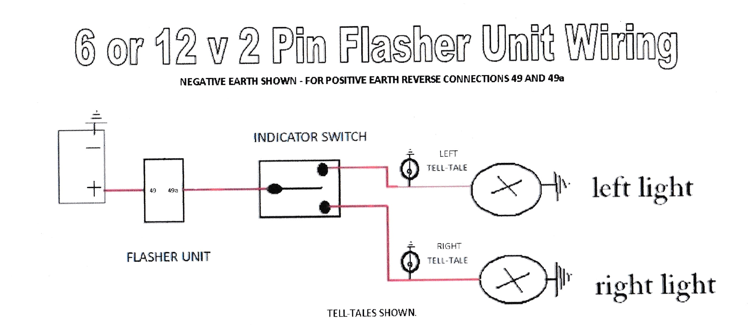
pettibone wire diagram my wiring diagram
