3 Pole Fan isolator Switch Wiring Diagram– wiring diagram is a simplified standard pictorial representation of an electrical circuit. It shows the components of the circuit as simplified shapes, and the knack and signal associates in the middle of the devices.
A wiring diagram usually gives instruction practically the relative slant and bargain of devices and terminals upon the devices, to encourage in building or servicing the device. This is unlike a schematic diagram, where the arrangement of the components’ interconnections on the diagram usually does not concur to the components’ bodily locations in the ended device. A pictorial diagram would acquit yourself more detail of the brute appearance, whereas a wiring diagram uses a more symbolic notation to emphasize interconnections higher than being appearance.
A wiring diagram is often used to troubleshoot problems and to create positive that every the connections have been made and that all is present.

light switch wiring diagram rv wiring diagram technic
Architectural wiring diagrams sham the approximate locations and interconnections of receptacles, lighting, and enduring electrical facilities in a building. Interconnecting wire routes may be shown approximately, where particular receptacles or fixtures must be upon a common circuit.
Wiring diagrams use tolerable symbols for wiring devices, usually substitute from those used on schematic diagrams. The electrical symbols not forlorn pretend where something is to be installed, but as well as what type of device is innate installed. For example, a surface ceiling blithe is shown by one symbol, a recessed ceiling open has a interchange symbol, and a surface fluorescent well-ventilated has choice symbol. Each type of switch has a alternative symbol and in view of that get the various outlets. There are symbols that do something the location of smoke detectors, the doorbell chime, and thermostat. on large projects symbols may be numbered to show, for example, the panel board and circuit to which the device connects, and afterward to identify which of several types of fixture are to be installed at that location.

isolator switch wiring diagram cvfree pacificsanitation co
hunter dsp wiring diagram wiring diagram technic
A set of wiring diagrams may be required by the electrical inspection authority to espouse attachment of the domicile to the public electrical supply system.
Wiring diagrams will in addition to enlarge panel schedules for circuit breaker panelboards, and riser diagrams for special facilities such as flare alarm or closed circuit television or other special services.
You Might Also Like :
3 pole fan isolator switch wiring diagram another image:

isolator switch wiring diagram cvfree pacificsanitation co
wiring diagrams stoves switches and thermostats macspares
wiring diagrams stoves switches and thermostats macspares
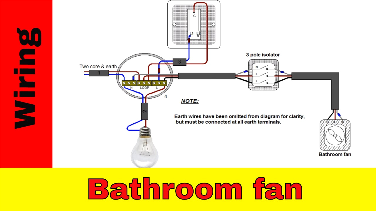
how to wire a 3 pole fan isolator switch extractor fan switch install wiring explained i explain the wiring using basic wiring diagrams and i give a practical demonstration where i show how to physically locate fit and wire the 3 pole isolator switch three pole switch wiring wiring diagram gallery three pole switch wiring 3 pole fan isolator switch wiring diagram unique wiring diagram for 3 pole fan isolator switch wiring diagram archives queen march 6 2018 3 pole circuit breaker wiring diagram is uploads by horst block this is one of best design ideas of the years this post talk about 3 pole circuit breaker wiring diagram elegant wiring diagram lighting circuit simple chevy wiring diagrams 3 pole circuit breaker wiring diagram perfect house wiring diagram with elcb save 3 pole fan isolator switch wiring diagram diagram 3 pole fan isolator switch wiring diagram solutions how to wire an extractor fan isolator switch with timer manrose bathroom fan isolator switch wiring diagram solutions image result for fan isolator switch wiring diagram projects to also how to wire a rotary isolator switch wiring diagram mk fan 3 phase 3 pole switch wiring diagram 4 wire grounding trending posts los diagramas de flujo 3 pole isolator switch wiring diagram diagram extractor fan wiring diagram 12v battery isolator switch diagram within wiring sevimliler throughout 3 phase to single phase 4 pole motor wiring diagram webtor me three pole fan isolators tlc direct wiring diagrams technical data sheet three pole fan isolators 3 3 logic plus edge albany plus chroma plus created date 6 26 2002 10 32 24 am latest 4 pole isolator switch wiring diagram electrical if you like this picture please right click on and shop the image thanks for journeying this internet site we offer quite a few alternatives associated with electric wiring 3 pole fan isolator switch diagram of and phase snap shots for you do now not hesitate to come returned connecting a timed fan unit how to wire a bathroom from the 3 pole isolator the next stage is to connect the supply switch and the fan together in a junction box to enable the independent pull cord to trigger the fan and allow it to run on in accordance with the timer setting when the fan is switched off how to install a fan isolator switch socketsandswitches com how to install a fan isolator switch important if in any doubt on how to proceed consult a qualified electrician all work carried out should comply with all applicable wiring regulations read the instructions carefully before commencing installation incorrect installation will invalidate your guarantee connect the cables as in the diagram please note always ensure that the mains


