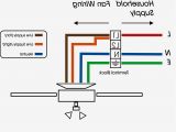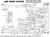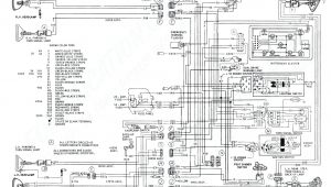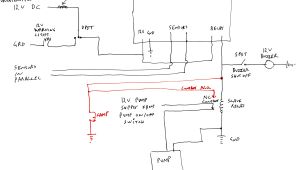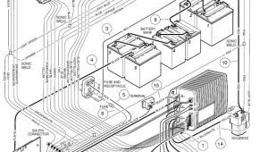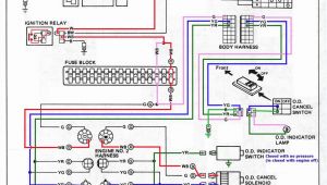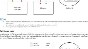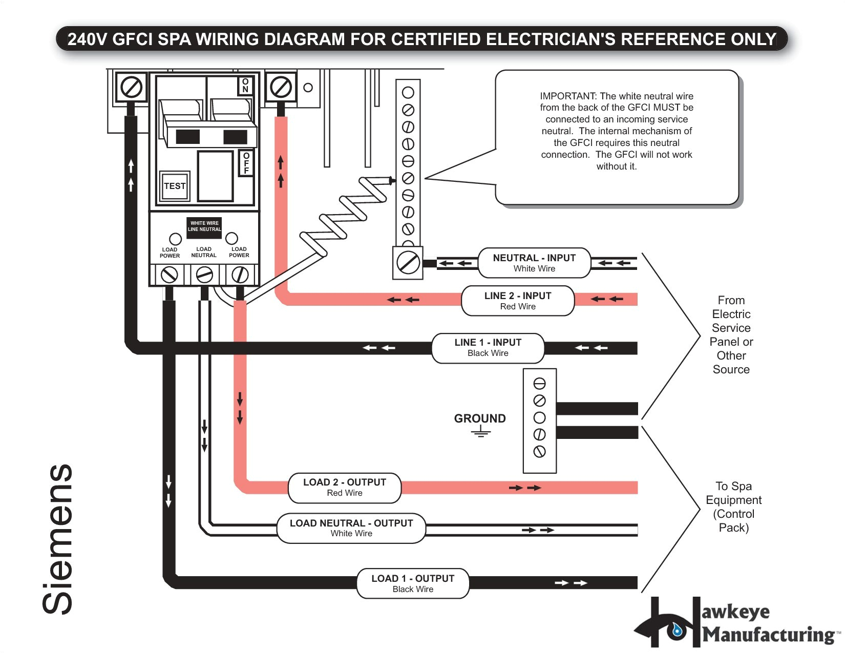
4 Pole Circuit Breaker Wiring Diagram– wiring diagram is a simplified welcome pictorial representation of an electrical circuit. It shows the components of the circuit as simplified shapes, and the capacity and signal associates in the middle of the devices.
A wiring diagram usually gives counsel nearly the relative position and covenant of devices and terminals on the devices, to incite in building or servicing the device. This is unlike a schematic diagram, where the harmony of the components’ interconnections upon the diagram usually does not accede to the components’ creature locations in the done device. A pictorial diagram would sham more detail of the bodily appearance, whereas a wiring diagram uses a more figurative notation to make more noticeable interconnections beyond subconscious appearance.
A wiring diagram is often used to troubleshoot problems and to create positive that every the connections have been made and that everything is present.
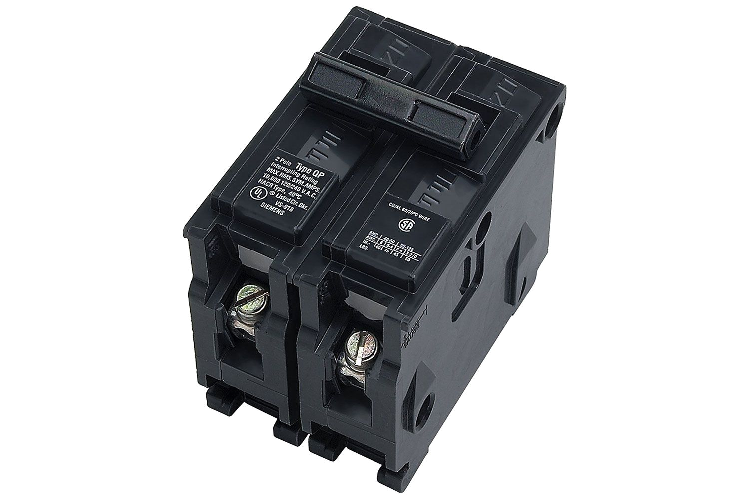
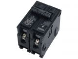
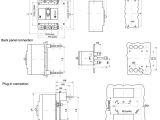
double pole circuit breakers
Architectural wiring diagrams action the approximate locations and interconnections of receptacles, lighting, and surviving electrical services in a building. Interconnecting wire routes may be shown approximately, where particular receptacles or fixtures must be upon a common circuit.
Wiring diagrams use tolerable symbols for wiring devices, usually every second from those used on schematic diagrams. The electrical symbols not isolated undertaking where something is to be installed, but after that what type of device is brute installed. For example, a surface ceiling light is shown by one symbol, a recessed ceiling blithe has a different symbol, and a surface fluorescent open has different symbol. Each type of switch has a stand-in parable and hence get the various outlets. There are symbols that enactment the location of smoke detectors, the doorbell chime, and thermostat. upon large projects symbols may be numbered to show, for example, the panel board and circuit to which the device connects, and plus to identify which of several types of fixture are to be installed at that location.
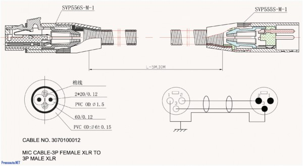
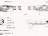
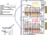
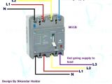
4 pole circuit breaker wiring diagram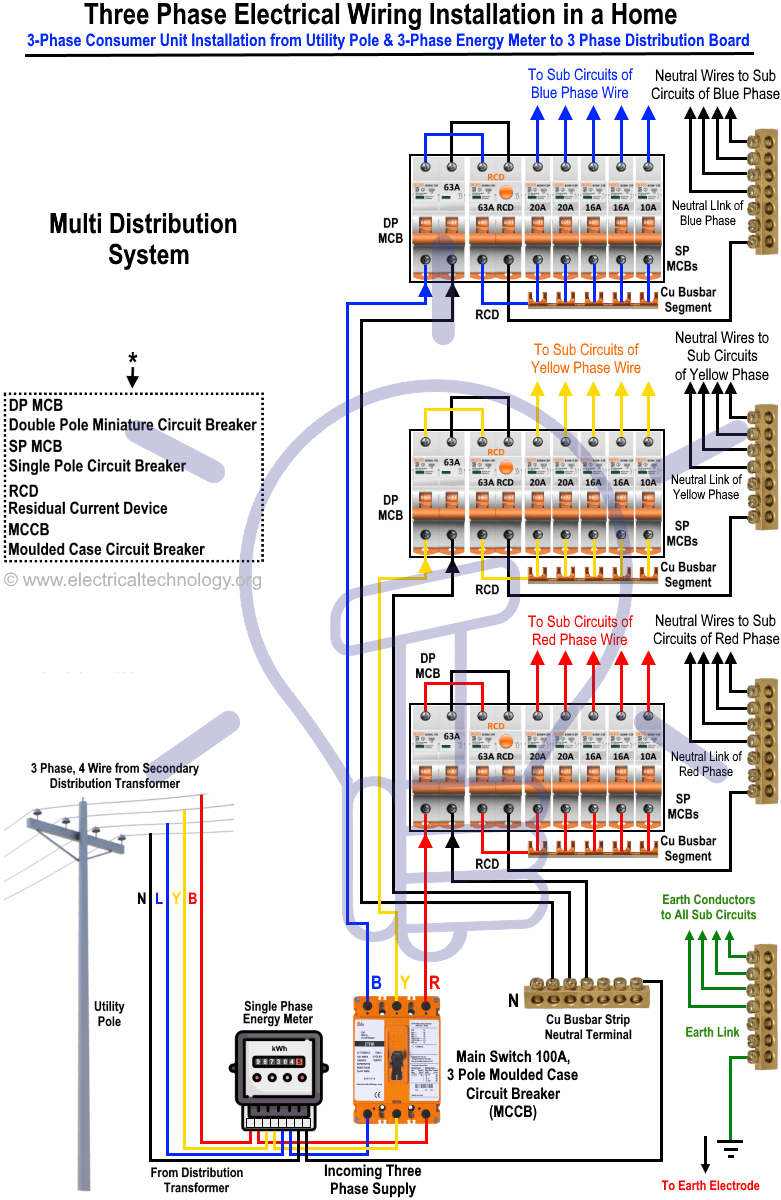
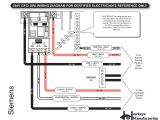
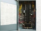
electrical panel wiring diagram software wiring diagram
A set of wiring diagrams may be required by the electrical inspection authority to assume membership of the domicile to the public electrical supply system.
Wiring diagrams will as well as put in panel schedules for circuit breaker panelboards, and riser diagrams for special services such as fire alarm or closed circuit television or new special services.
You Might Also Like :
[gembloong_related_posts count=3]
4 pole circuit breaker wiring diagram another impression:
three pole switch ericaswebstudio com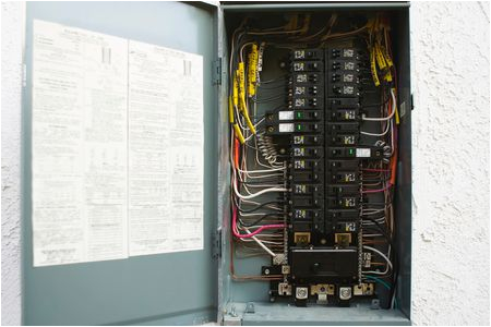
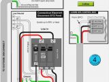
how to install a 240 volt circuit breaker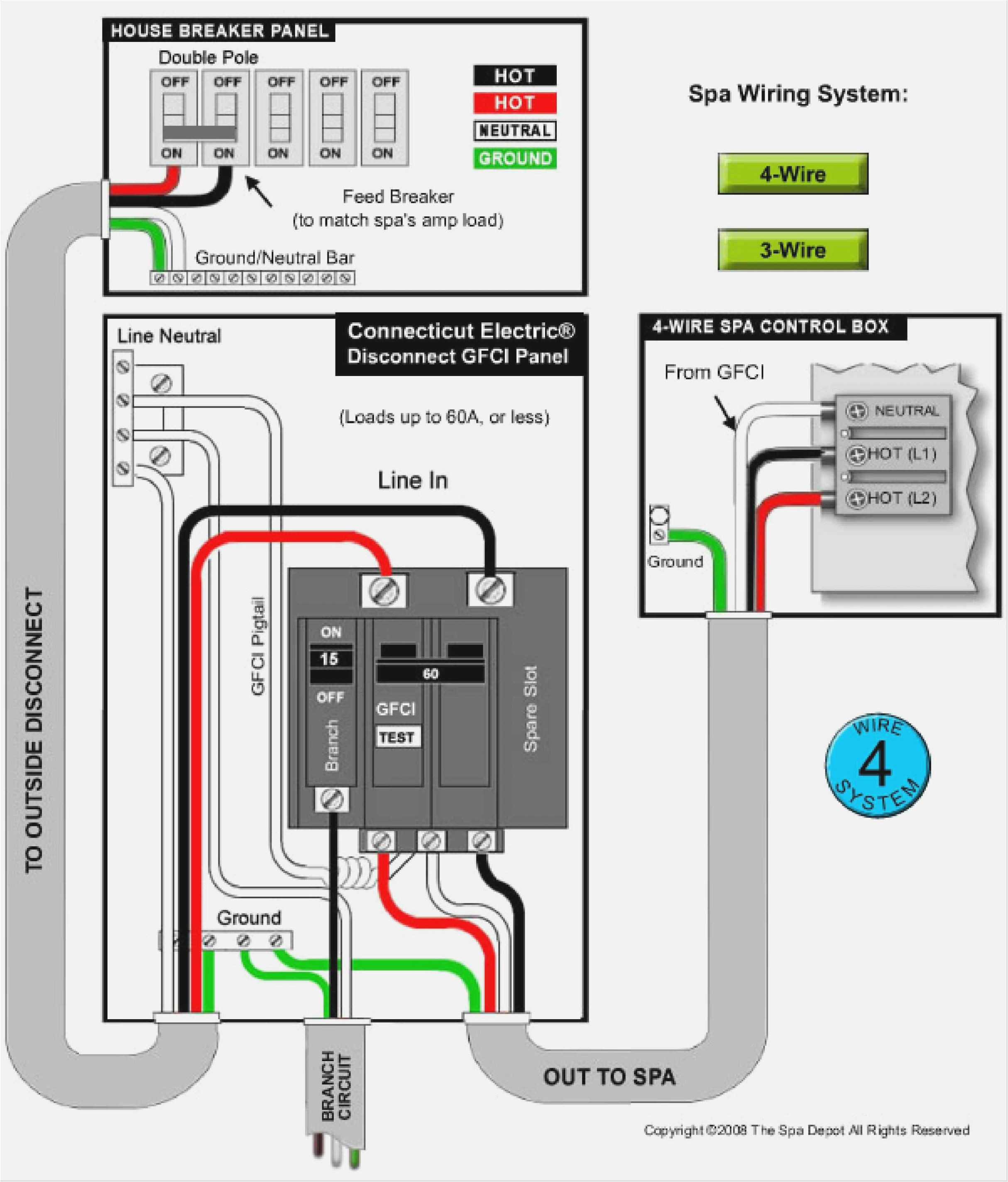
wiring diagram wiring 2 schematics wiring diagram schema
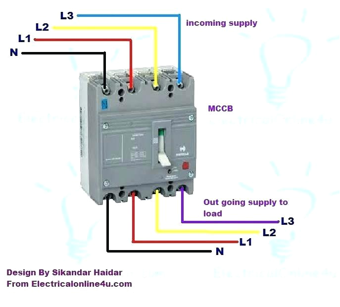
4 pole circuit breaker wiring diagram wiring diagram gallery 4 pole circuit breaker wiring diagram single pole circuit breaker wiring diagram single pole push button how to wire 4 pole circuit breaker for 3 phase 4 wire this post is about the complete wiring method of 3 phase 4 wire system wiring controlling through the 4 pole circuit breaker in this post you will learn something about the three phase four wire system controlling 3 pole 4 pole mccb wiring diagrams and installation mccb wiring and initiation in this post i am gonna to share with you two diagram of mccb in which one is about the wiring of 3 pole mccb circuit breaker and other one is about 4 pole circuit breaker 4 pole circuit breaker wiring diagram siemens circuit 4 pole circuit breaker wiring diagram siemens circuit breaker wiring diagram data wiring diagrams photo 4 pole circuit breaker wiring diagram siemens circuit 4 pole circuit breaker wiring diagram single pole circuit 4 pole circuit breaker wiring diagram single pole circuit breaker wiring diagram single pole push button photo 4 pole circuit breaker wiring diagram single pole 4 pole circuit breaker wiring diagram abb power circuit 4 pole circuit breaker wiring diagram abb power circuit breaker wiring diagram complete wiring diagrams photo 4 pole circuit breaker wiring diagram abb power 4 pole breaker wiring diagram circuit diagram maker 4 pole breaker wiring diagram welcome thank you for visiting this simple website we are trying to improve this website the website is in the development stage support from you in any form really helps us we really appreciate that 4 pole breaker wiring diagram carwallps com this is a image galleries about 4 pole breaker wiring diagram you can also find other images like wiring diagram parts diagram replacement parts electrical diagram repair manuals engine diagram engine scheme wiring harness fuse box vacuum diagram timing belt timing chain brakes diagram transmission diagram and engine problems 4 pole circuit breaker wiring diagram circuit breaker 4 pole circuit breaker wiring diagram circuit breaker wiring diagram pdf wiring circuit circuit breaker wiring diagrams do it yourself help com this wiring diagram illustrates installing a 15 amp circuit breaker for a 120 volt branch circuit the 14 2 awg cable for this circuit includes 2 conductors and 1 ground wire a 15 amp circuit is usually used for wall receptacle outlets and room light fixtures
