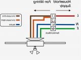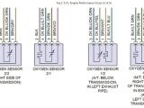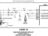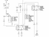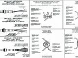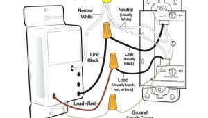
4 Wire Oxygen Sensor Diagram– wiring diagram is a simplified all right pictorial representation of an electrical circuit. It shows the components of the circuit as simplified shapes, and the talent and signal associates amongst the devices.
A wiring diagram usually gives information approximately the relative perspective and union of devices and terminals upon the devices, to put up to in building or servicing the device. This is unlike a schematic diagram, where the union of the components’ interconnections upon the diagram usually does not correspond to the components’ instinctive locations in the ended device. A pictorial diagram would perform more detail of the inborn appearance, whereas a wiring diagram uses a more figurative notation to play up interconnections greater than physical appearance.
A wiring diagram is often used to troubleshoot problems and to create certain that all the connections have been made and that whatever is present.
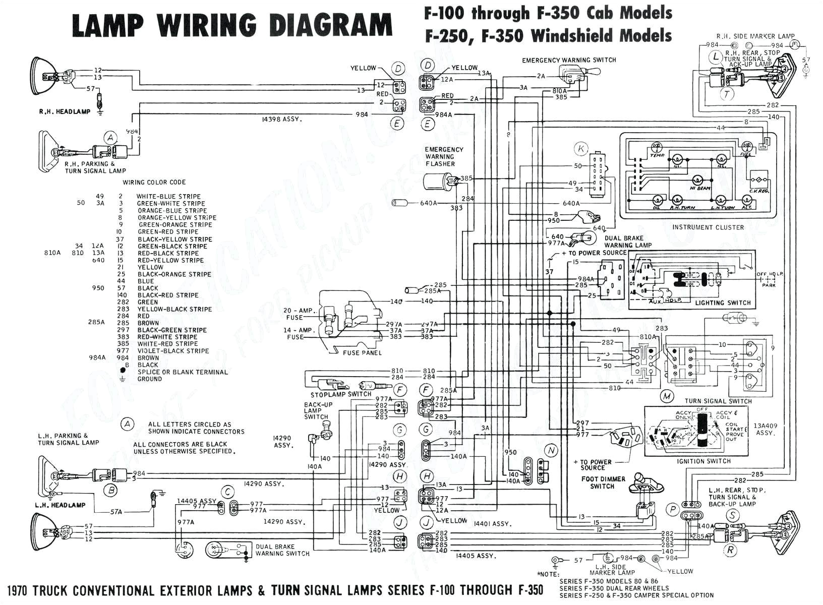
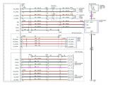
nippondenso oxygen sensor wiring diagram list of schematic circuit
Architectural wiring diagrams put-on the approximate locations and interconnections of receptacles, lighting, and unshakable electrical services in a building. Interconnecting wire routes may be shown approximately, where particular receptacles or fixtures must be upon a common circuit.
Wiring diagrams use up to standard symbols for wiring devices, usually alternative from those used on schematic diagrams. The electrical symbols not lonely fake where something is to be installed, but then what type of device is living thing installed. For example, a surface ceiling well-ventilated is shown by one symbol, a recessed ceiling roomy has a rotate symbol, and a surface fluorescent vivacious has complementary symbol. Each type of switch has a alternative story and as a result pull off the various outlets. There are symbols that show the location of smoke detectors, the doorbell chime, and thermostat. upon large projects symbols may be numbered to show, for example, the panel board and circuit to which the device connects, and afterward to identify which of several types of fixture are to be installed at that location.
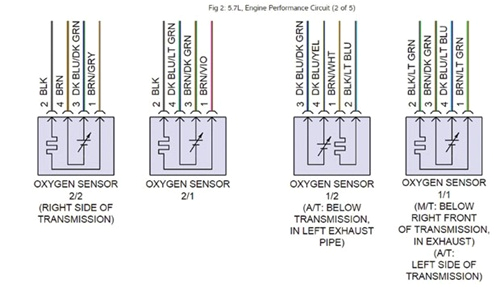
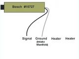
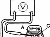
diagram of oxygen sensor wiring diagram data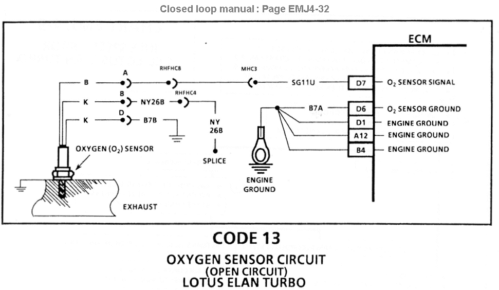
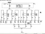
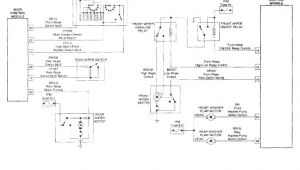
o2 sensor wiring diagram schema wiring diagram preview
A set of wiring diagrams may be required by the electrical inspection authority to take up membership of the quarters to the public electrical supply system.
Wiring diagrams will furthermore attach panel schedules for circuit breaker panelboards, and riser diagrams for special services such as flame alarm or closed circuit television or extra special services.
You Might Also Like :
- 2006 Honda Ridgeline Trailer Wiring Diagram
- Kicker Comp D Wiring Diagram
- Typical Wiring Diagram Walk In Cooler
4 wire oxygen sensor diagram another picture:
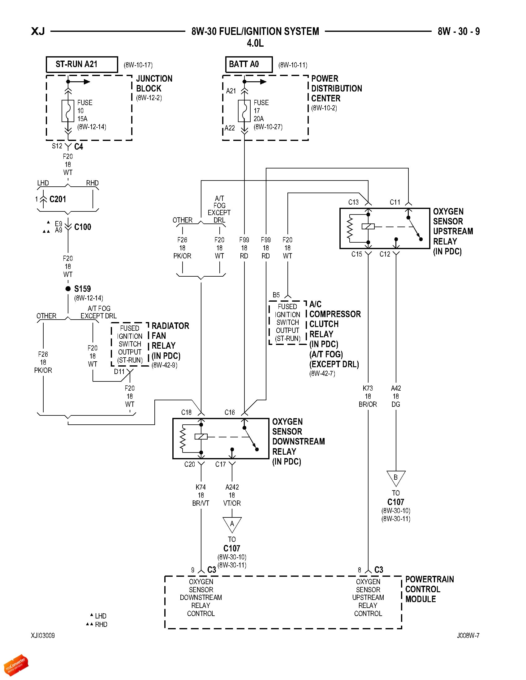
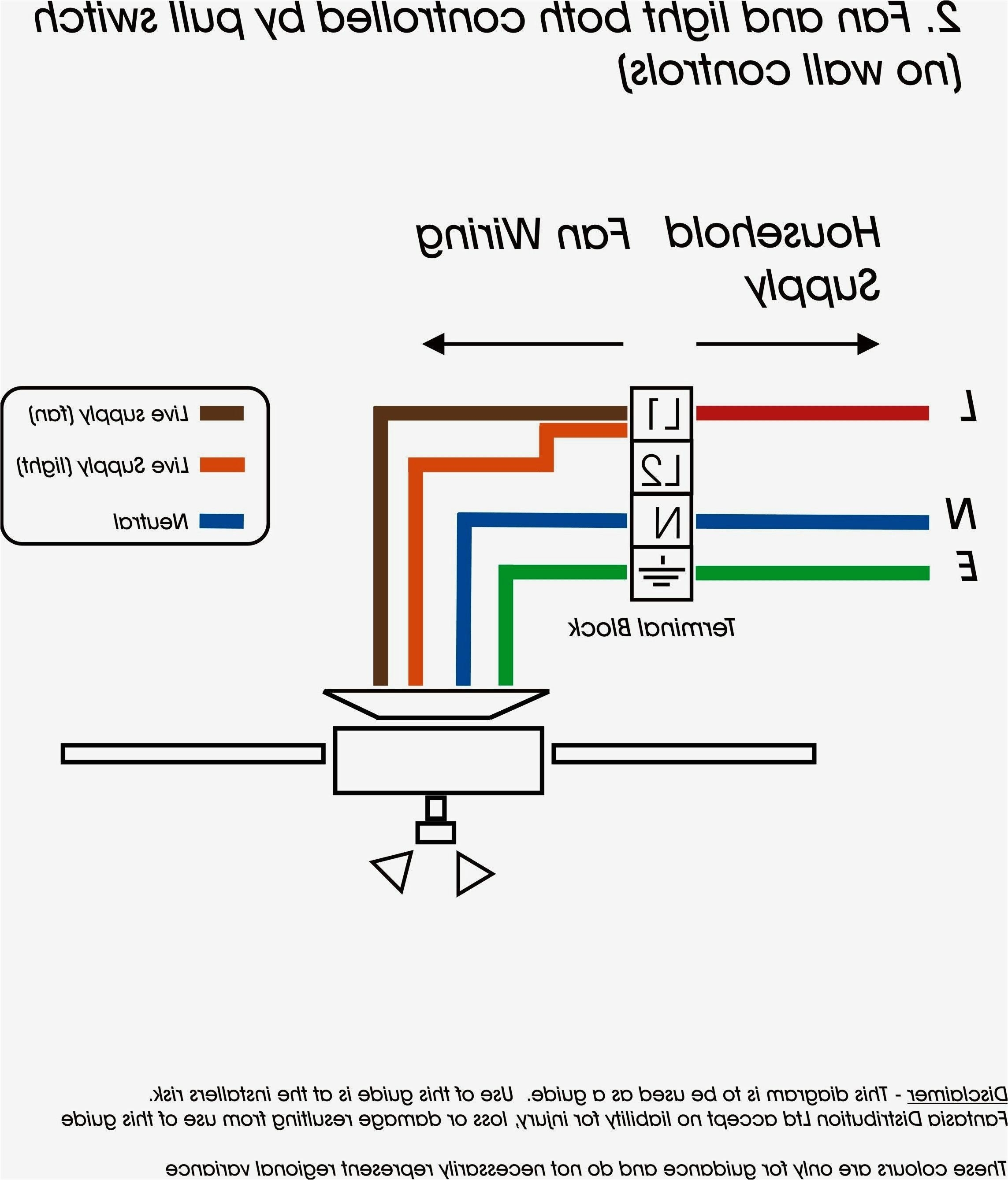
02 sensor wiring diagram free download schematic wiring diagram site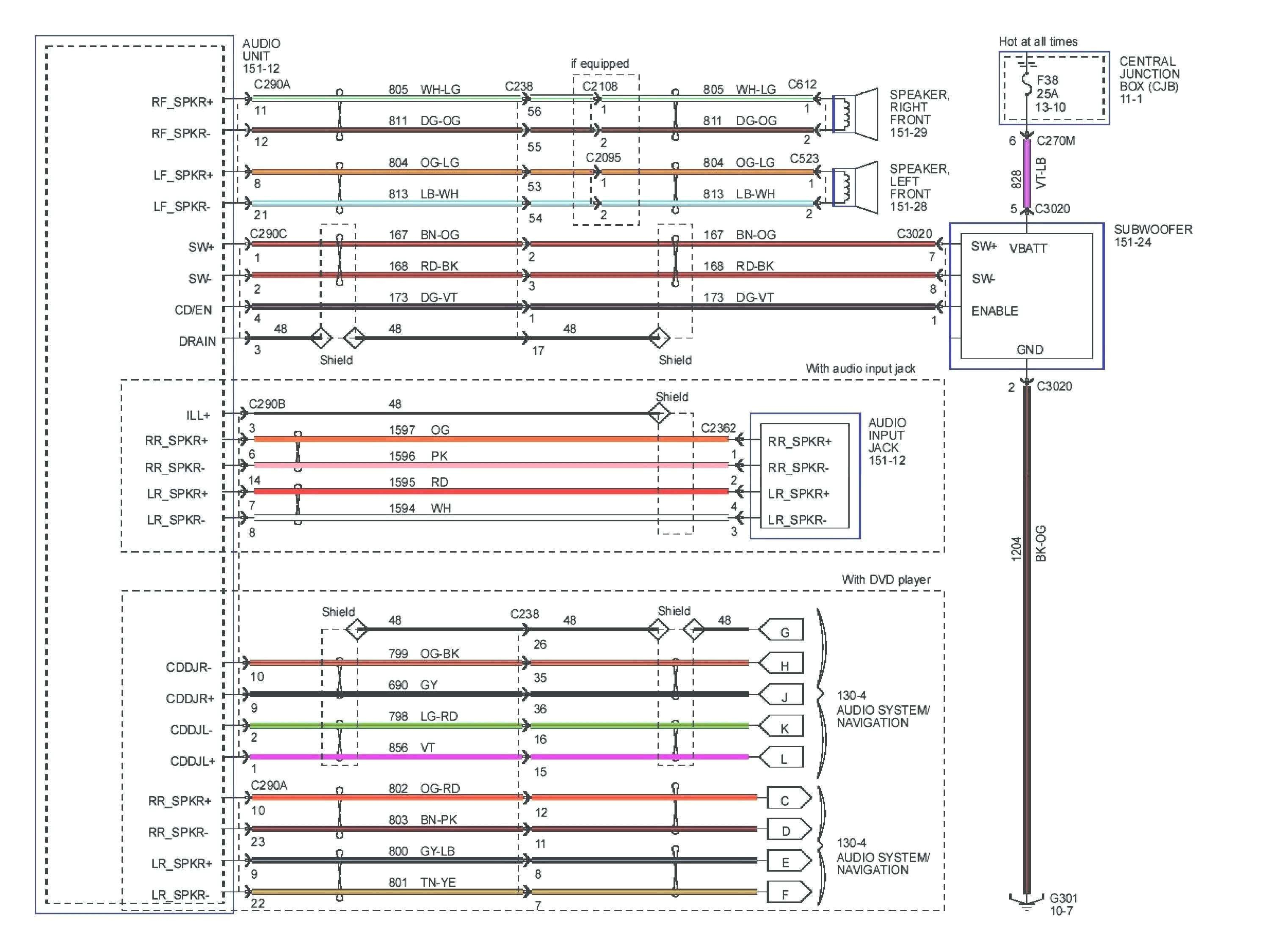
civic o2 sensor wiring diagram wiring library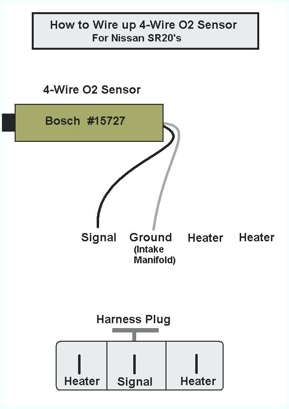
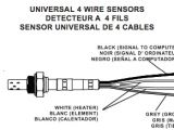
4 wire oxygen sensor schematic wiring diagram
can anybody check a 4 wire oxygen sensor can anybody check a 4 wire oxygen sensor here s how to check a 4 wire oxygen sensor this is the second part of testing your oxygen sensor wiring and sensors megamanual com relays generally have 4 pins marked 85 86 30 87 or 5 pins 85 86 30 87 87a for most automotive relays pins 85 and 86 are the coil circuit and takes 12 volts to activate the switch assuming a 12v rated relay of course bmw e46 oxygen sensor replacement pelican parts locate the oxygen sensor electrical connectors at the right side of the engine above the exhaust manifold green arrows label or mark the connectors to help during the reinstallation process p0420 oxygen sensor simulator hack 7 steps the catalytic converter s performance is measured by the secondary oxygen sensor if the output is less than 95 it throws the p0420 code graphing the output on an obdii scanner shows an erratic curve with varying amplitude and frequency pressure sensor wiring diagram youtube pressure sensor wiring diagram amazon printed books https www createspace com 3623928 amazon kindle edition http www amazon com automotive elec quickstart manual documents holley com 5 locate a position for the oxygen sensor as close to the engine as possible the oxygen sensor should be mounted at a point where it can read a good average of all the cylinders on one bank pirani gauge wikipedia structure the pirani gauge consists of a metal sensor wire usually gold plated tungsten or platinum suspended in a tube which is connected to the system whose vacuum is to be measured ecumaster emu black technology the emu black is assembled according to ipc s 815a standards to ensure high reliability of the product the device is manufactured on an automated assembly line with optical inspection automatically tested including burn in engine control module and sensor locations axleaddict the baro sensor measures the ambient air pressure which tells the ecm the current altitude of the vehicle if you re driving in the mountains you ll need less fuel because there is less oxygen in the atmosphere and therefore less oxygen in the engine cylinder dulcotest sensors for free chlorine prominent reliable online measurement of free effective chlorine with the versatile dulcotest sensors free chlorine is the most important disinfectant in the world
