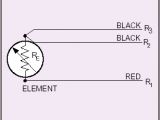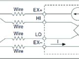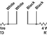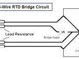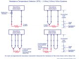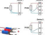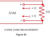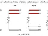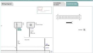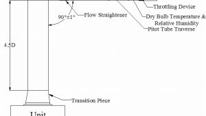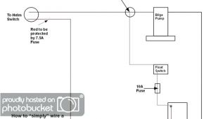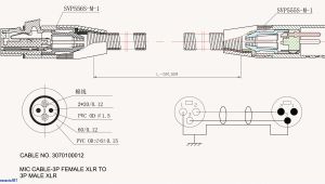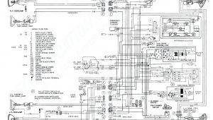
4 Wire Pt100 Wiring Diagram– wiring diagram is a simplified adequate pictorial representation of an electrical circuit. It shows the components of the circuit as simplified shapes, and the capacity and signal connections between the devices.
A wiring diagram usually gives recommendation practically the relative point and conformity of devices and terminals on the devices, to put up to in building or servicing the device. This is unlike a schematic diagram, where the understanding of the components’ interconnections on the diagram usually does not grant to the components’ physical locations in the over and done with device. A pictorial diagram would proceed more detail of the swine appearance, whereas a wiring diagram uses a more figurative notation to play up interconnections higher than being appearance.
A wiring diagram is often used to troubleshoot problems and to make distinct that every the friends have been made and that anything is present.
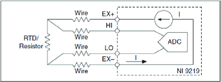
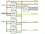
oc 8009 rtd wiring diagrams wiring diagram
Architectural wiring diagrams perform the approximate locations and interconnections of receptacles, lighting, and enduring electrical facilities in a building. Interconnecting wire routes may be shown approximately, where particular receptacles or fixtures must be on a common circuit.
Wiring diagrams use gratifying symbols for wiring devices, usually stand-in from those used on schematic diagrams. The electrical symbols not on your own put-on where something is to be installed, but plus what type of device is bodily installed. For example, a surface ceiling open is shown by one symbol, a recessed ceiling fresh has a substitute symbol, and a surface fluorescent blithe has substitute symbol. Each type of switch has a swap story and thus accomplish the various outlets. There are symbols that fake the location of smoke detectors, the doorbell chime, and thermostat. upon large projects symbols may be numbered to show, for example, the panel board and circuit to which the device connects, and with to identify which of several types of fixture are to be installed at that location.
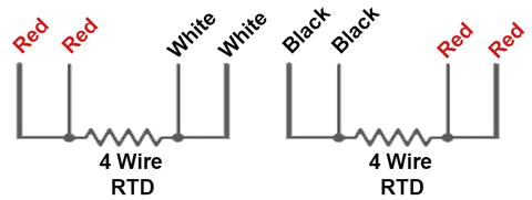
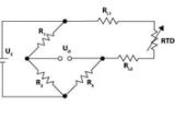
4 wire rtd evolution sensors and controls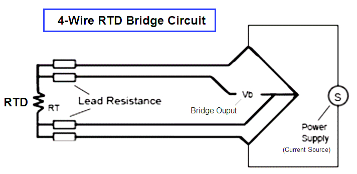
oc 8009 rtd wiring diagrams wiring diagram
A set of wiring diagrams may be required by the electrical inspection authority to espouse connection of the address to the public electrical supply system.
Wiring diagrams will as well as intensify panel schedules for circuit breaker panelboards, and riser diagrams for special services such as fire alarm or closed circuit television or additional special services.
You Might Also Like :
[gembloong_related_posts count=3]
4 wire pt100 wiring diagram another photograph:
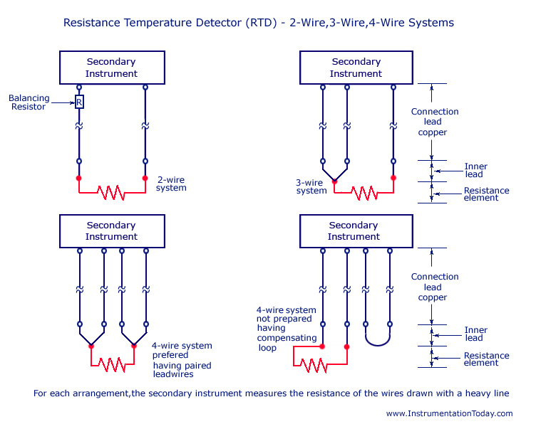
resistance temperature detector rtd working types 2 3 and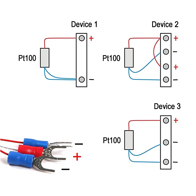
atoplee 1pc edelstahl wasserdicht pt100 ohm probe sensor l
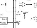
rtd elements and sensors introduction and tables
pt100 in 2 3 or 4 wire connection wika blog the highest measurement accuracies are only achievable with a pt100 in a 4 wire connection a pt1000 measuring element in class a also offers good measurement accuracies in a 2 wire connection and represents an economical alternative to 3 or 4 wire connections for machine building note further information on resistance thermometers can be found on our website please also watch the following pt100 wiring for your industrial temperture sensors pt100 wiring methods 2 3 or 4 wire the wiring of a pt100 temperature is different to other temperature sensors in particular thermocouples it is important to get the wiring of your sensor correct otherwise the measuring instrument may give an incorrect reading or no reading at all conductor material cables used for connecting a pt100 temperature sensor usually have copper based rtd module and pt100 wiring module optional when wiring with two wires first jumper across a1 and b1and a2 and b2 respectively then connect pt100 sensors and to the rtd module according to the following diagram on the left note a1b1 a2b2 and c1c2 have the same wire color to connect the three wires directly connect the pt100 sensors to the rtd module according to the following diagram on the right note a1 a2 b1 b2 are the 4 wire rtd wiring diagram free wiring diagram collection of 4 wire rtd wiring diagram a wiring diagram is a streamlined conventional photographic representation of an electric circuit it shows the elements of the circuit as simplified forms and also the power and also signal links between the devices pt100 messwiderstand in 2 3 oder 4 leiter schaltung dabei gibt es drei moglichkeiten den pt100 an den messumformer anzuschliessen in 2 3 oder 4 leiterschaltung abb pt100 messwiderstand in 2 leiter schaltung pt100 in 2 leiter schaltung bei einer 2 leiter schaltung geht der widerstand der zuleitung als fehler in die messung ein als richtwert gilt bei kupferleitung mit querschnitt 0 22 mm 2 0 162 w m 0 42 c m bei pt100 bei where do those wires go pt100 vertex qis co uk where do those wires go pt100 1 a pt100 normally has 3 wires it is in simple terms a resistance that changes with temperature 2 it is called a pt100 because at 0 deg c it will measure 100 ohms 3 at ambient it will be around 138 ohms 4 because a very small change in resistance happens with each degree in temperature the 4 wire rtd wiring a 4 wire rtd thermometrics corporation 4 wire rtd wiring diagram in this circuit there are three leads coming from the rtd instead of two l1 and l3 carry the measuring current while l2 acts only as a potential lead no current flows through it while the bridge is in balance since l1 and l3 are in separate arms of the bridge resistance is canceled this circuit assumes high impedance at eo and close matching of resistance between 2 3 and 4 wire rtds what is the difference what is the difference between a 2 3 and 4 wire rtd published april 17 2019 down rtd circuits work by sending a known amount of current through an rtd sensor and then measuring the voltage drop across that resistor at the given temperature because every pt100 element in the circuit containing the sensing element including the lead wires connectors and the measuring instrument itself rtd pt100 3 wire wiring diagram free wiring diagram assortment of rtd pt100 3 wire wiring diagram a wiring diagram is a streamlined standard photographic depiction of an electrical circuit it shows the components of the circuit as streamlined shapes and also the power and also signal links between the gadgets 2 3 4 wire rtd measurement texas instruments 2 3 4 wire rdt pt100 to pt1000 temperature measurement rtd sensors most common pt100 pt500 pt1000 rtd resistance temperature device linear resistance change with temperature positive temperature coefficient wire wound or thick film metal resistor over limited temperature range advantages accuracy available to 0 1 c high linearity over limited temperature
