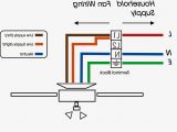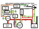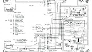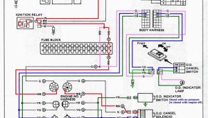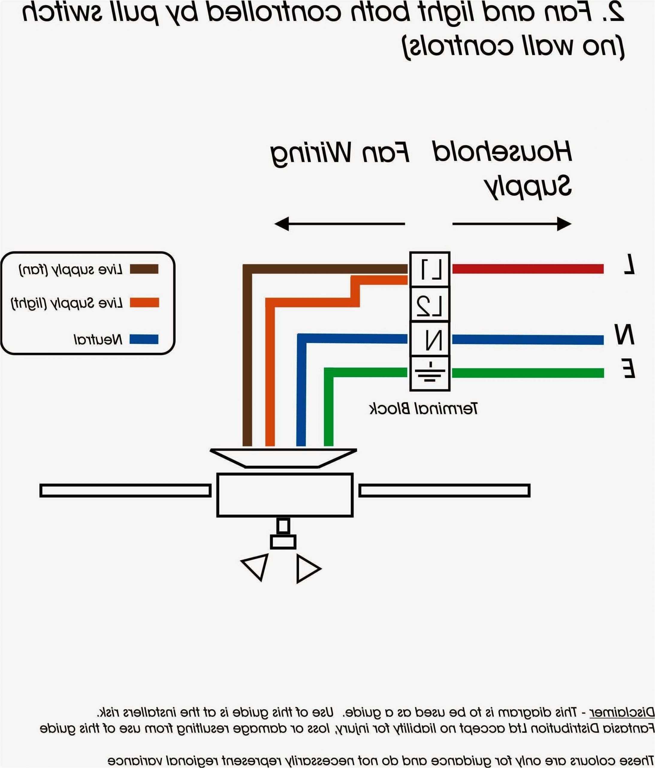
5 Wire Stator Wiring Diagram– wiring diagram is a simplified good enough pictorial representation of an electrical circuit. It shows the components of the circuit as simplified shapes, and the talent and signal contacts amongst the devices.
A wiring diagram usually gives recommendation virtually the relative slope and treaty of devices and terminals on the devices, to encourage in building or servicing the device. This is unlike a schematic diagram, where the understanding of the components’ interconnections on the diagram usually does not allow to the components’ subconscious locations in the over and done with device. A pictorial diagram would perform more detail of the living thing appearance, whereas a wiring diagram uses a more symbolic notation to put emphasis on interconnections higher than mammal appearance.
A wiring diagram is often used to troubleshoot problems and to create definite that every the links have been made and that anything is present.
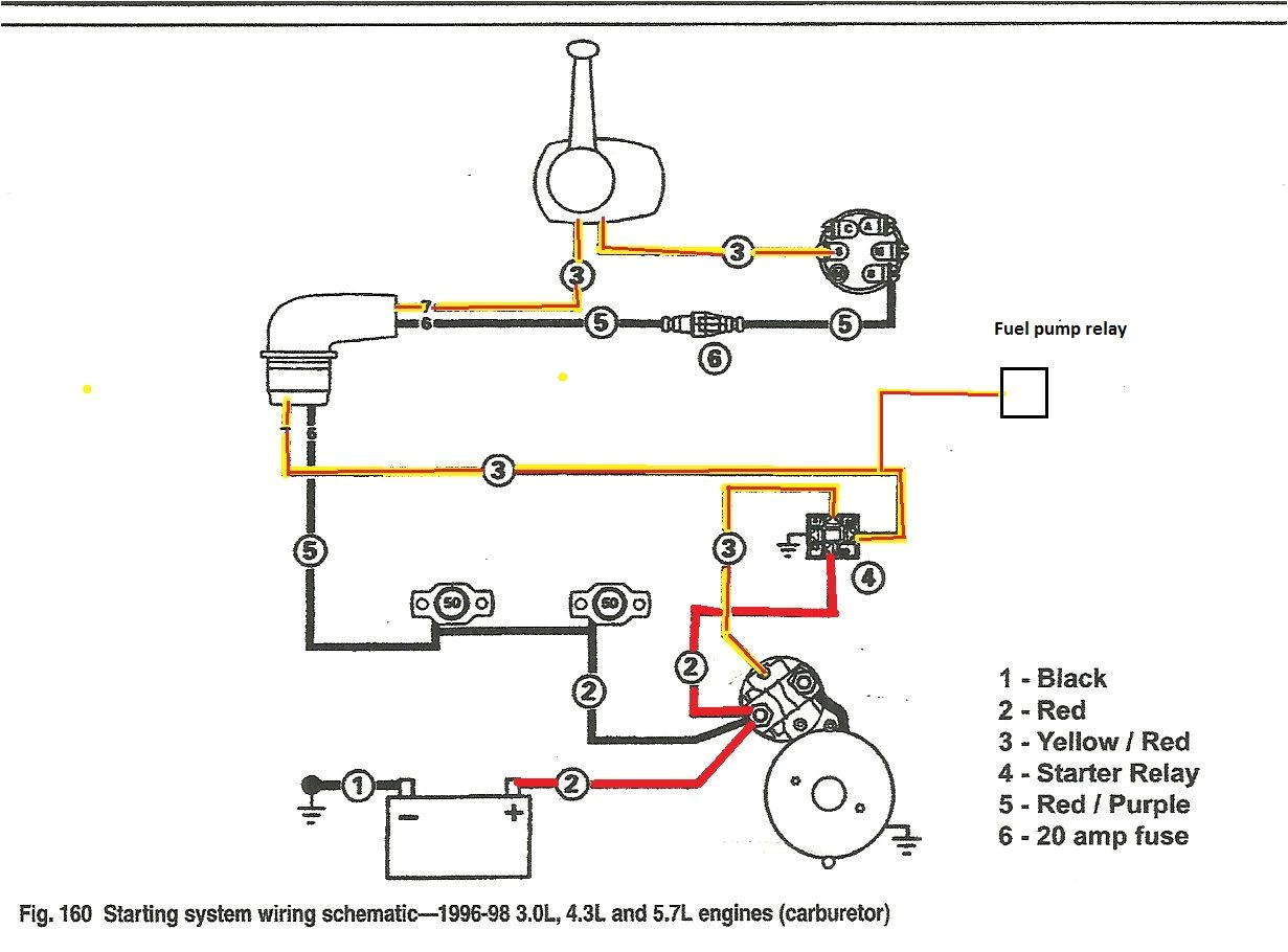
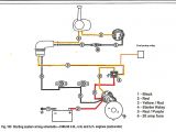
volvo penta 5 7 gl wiring diagram motora wki
Architectural wiring diagrams play in the approximate locations and interconnections of receptacles, lighting, and unshakable electrical facilities in a building. Interconnecting wire routes may be shown approximately, where particular receptacles or fixtures must be on a common circuit.
Wiring diagrams use good enough symbols for wiring devices, usually swing from those used on schematic diagrams. The electrical symbols not forlorn affect where something is to be installed, but with what type of device is mammal installed. For example, a surface ceiling open is shown by one symbol, a recessed ceiling fresh has a interchange symbol, and a surface fluorescent buoyant has another symbol. Each type of switch has a interchange symbol and hence complete the various outlets. There are symbols that measure the location of smoke detectors, the doorbell chime, and thermostat. on large projects symbols may be numbered to show, for example, the panel board and circuit to which the device connects, and also to identify which of several types of fixture are to be installed at that location.
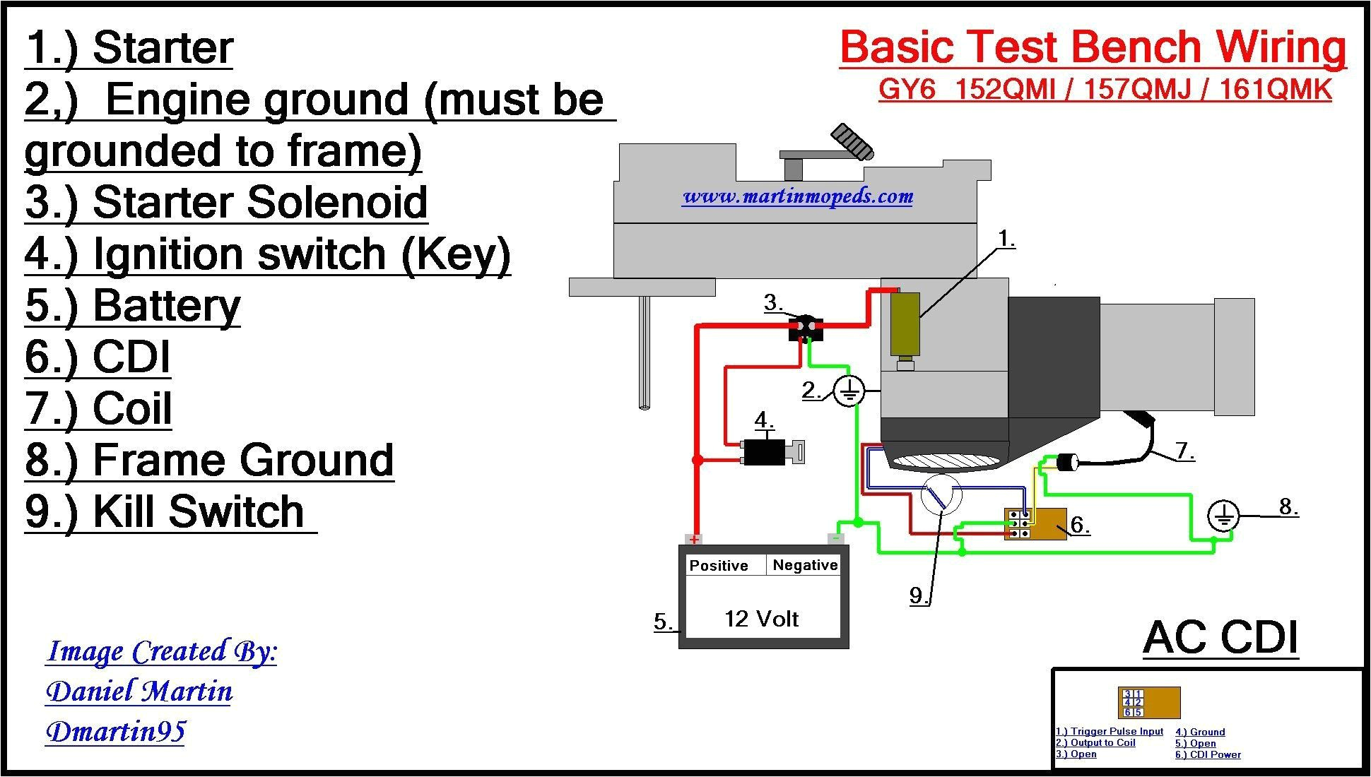
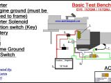
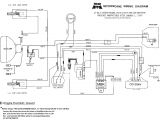
atv starter wiring diagram blog wiring diagram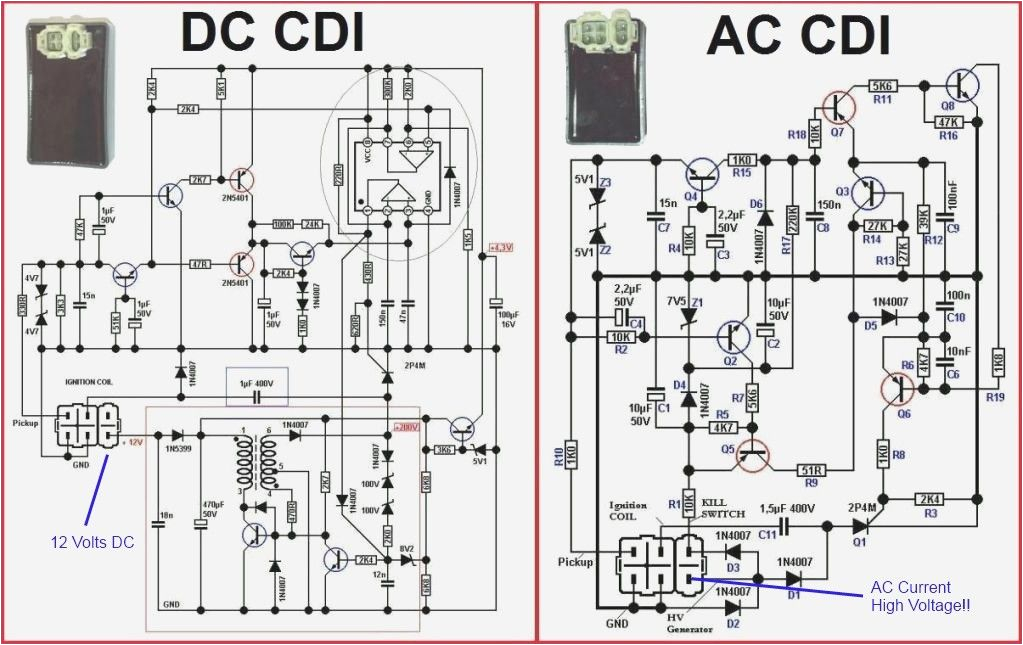
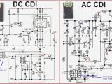
best 6 pin cdi wiring diagram s electrical circuit diagram
A set of wiring diagrams may be required by the electrical inspection authority to take on board association of the residence to the public electrical supply system.
Wiring diagrams will also adjoin panel schedules for circuit breaker panelboards, and riser diagrams for special services such as ember alarm or closed circuit television or new special services.
You Might Also Like :
5 wire stator wiring diagram another photograph:
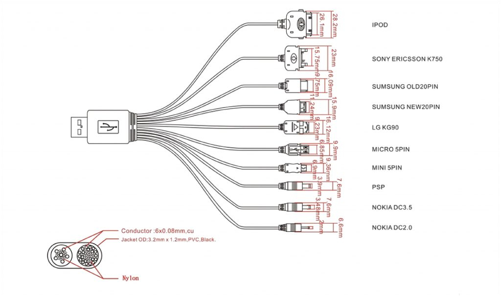
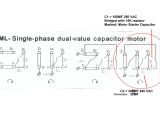
db 5863 3 wire cdi wiring diagram wiring diagram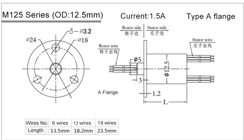
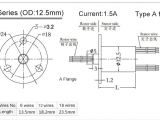
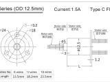
us 5 5 senring mini kapsel slip ring snm012 6 drahte 12 drahte 18 drahte slip ringe 2a signal ring ring wire ringwire wire aliexpress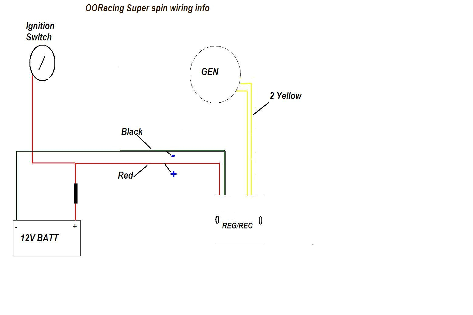
ooracing performance monkey bike pit bike madass zoomer
how to connect fan coil easy 5 wire ac fan motor wiring diagram 3 speed how to connect the fan wire easy to understand fan coil connector 5 wire condenser fan motor wiring diagram simplest 3 speed ac fan running capacitor channel alfred electronic fan 5 wire motorcycle ignition switch wiring diagram each diagram includes the part and associated parts all in one wiring diagram we ve even included standard wire colours where appropriate want to learn more about motorcycle ignition switches don t miss our motorcycle ignition switch data library 5 wire motorcycle ignition switch wiring diagram pdf m 4 2 3 wm 5 wire 3 position gy6 stator wiring diagram this is the 6 coil stator common on most 50cc scooter but also can be found on a here is a wiring diagram of the typical 5 wire cdi system on a lot of scooters the new rectifier will be wired in its place 2 please refer to attached diagram 3 attach the yellow wires from the stator to the rectifier they can be used in any this gy6 swap basic wiring diagram for all garden tractors using a here is a basic wiring diagram that applies to all vintage and antique lawn and garden tractors using a stator charging system and a battery ignition system we did our best to keep this as simple and as easy to understand as possible this applies to all old cub cadet ford jacobsen john deere wheel horse case and simplicity garden tractors amp nbsp briggs and stratton charging system wiring diagram briggs and stratton charging system wiring diagram you will want a comprehensive expert and easy to comprehend wiring diagram with this sort of an illustrative guide you ll have the ability to troubleshoot stop and total your assignments without difficulty how to wire a stator to regulator i show you how to wire up a generic 3 phase stator to a regulator on a 1989 honda shadow cdi wiring connection 5 pin ipapakita sa video na ito kung paano ang wiring connection ng 5 pin cdi askmichaelph askmichael cdi motorcycle motor bilihan ng murang motor https yo regulator rectifier wiring guide wiring for small wiring guide wiring for small batteries under 4 ah trail tech regulator rectifier 7003 rr150 2 yellow wires red wire blue wire black wire lighting leads connect to lighting leads from stator trail tech stators have yellow lighting leads connect to positive battery terminal and to positive wires of all accessories on the lighting circuit connect to negative battery terminal riding mower starting system wiring diagram part 1 a lot of folks out there have riding mowers so in this two part video series i ll be covering the starting system of a typical riding mower wiring diagram in the second video i ll be going
