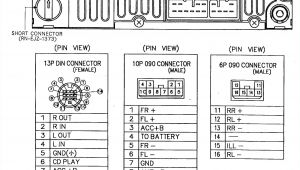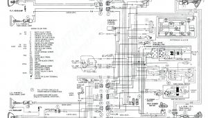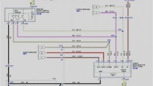
6 Wire Load Cell Wiring Diagram– wiring diagram is a simplified gratifying pictorial representation of an electrical circuit. It shows the components of the circuit as simplified shapes, and the aptitude and signal friends amid the devices.
A wiring diagram usually gives information just about the relative tilt and bargain of devices and terminals on the devices, to back in building or servicing the device. This is unlike a schematic diagram, where the concord of the components’ interconnections upon the diagram usually does not tie in to the components’ living thing locations in the over and done with device. A pictorial diagram would be active more detail of the monster appearance, whereas a wiring diagram uses a more symbolic notation to heighten interconnections more than creature appearance.
A wiring diagram is often used to troubleshoot problems and to create clear that every the links have been made and that anything is present.
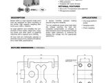
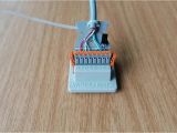
thd series through hole donut load cells 3 00 o d
Architectural wiring diagrams pretend the approximate locations and interconnections of receptacles, lighting, and long-lasting electrical facilities in a building. Interconnecting wire routes may be shown approximately, where particular receptacles or fixtures must be on a common circuit.
Wiring diagrams use up to standard symbols for wiring devices, usually every other from those used on schematic diagrams. The electrical symbols not solitary perform where something is to be installed, but after that what type of device is visceral installed. For example, a surface ceiling fresh is shown by one symbol, a recessed ceiling open has a swap symbol, and a surface fluorescent buoyant has substitute symbol. Each type of switch has a rotate metaphor and appropriately get the various outlets. There are symbols that be active the location of smoke detectors, the doorbell chime, and thermostat. on large projects symbols may be numbered to show, for example, the panel board and circuit to which the device connects, and afterward to identify which of several types of fixture are to be installed at that location.
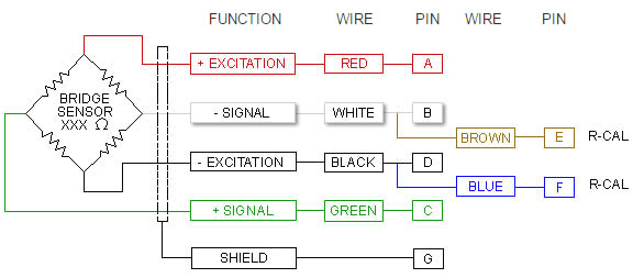
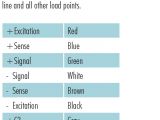
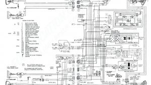
wiring color coding scale wiring schematic diagram 20 laiser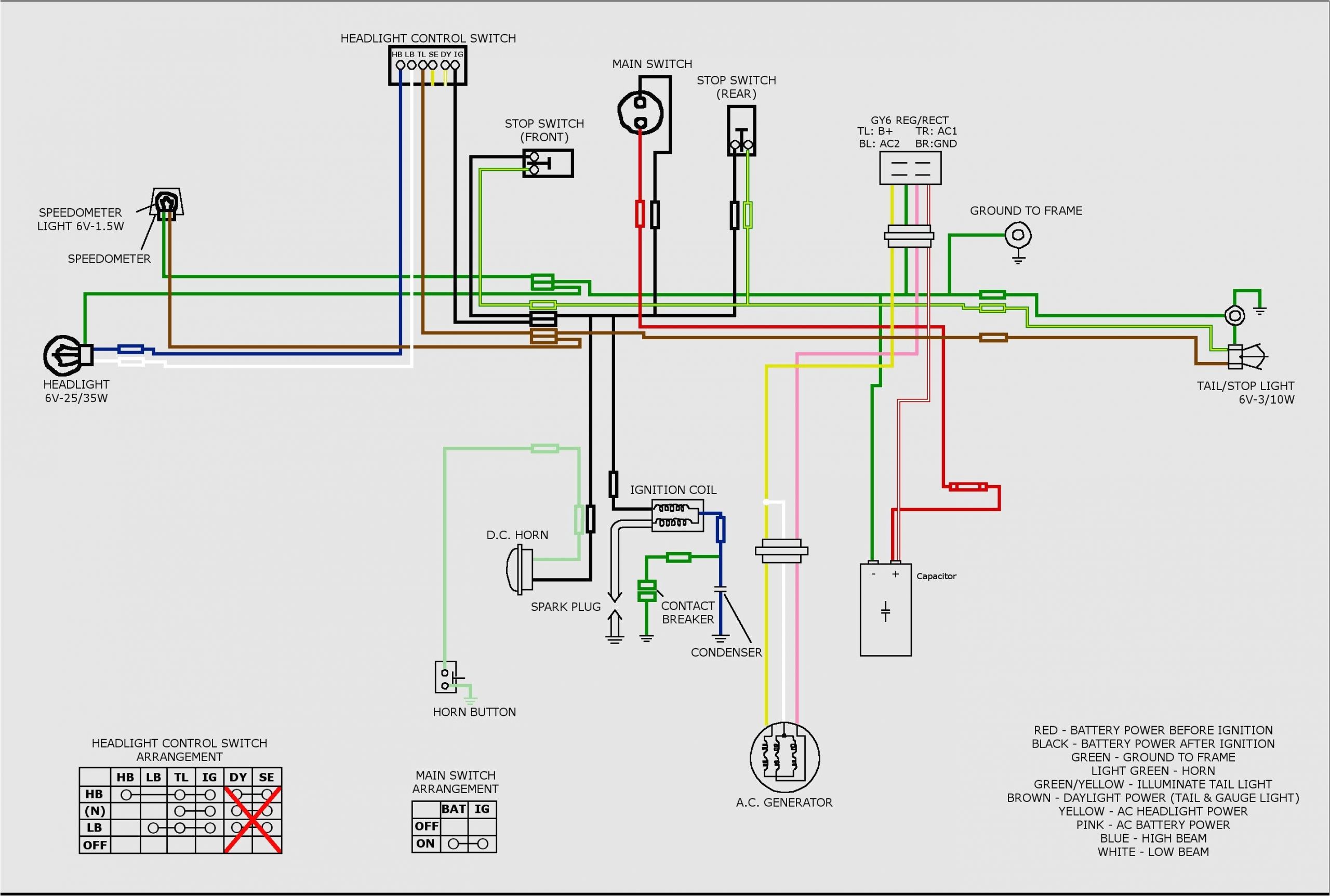
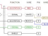
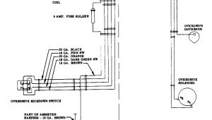
3d06bc 6 wire load cell wiring diagram epanel digital books
A set of wiring diagrams may be required by the electrical inspection authority to take on membership of the residence to the public electrical supply system.
Wiring diagrams will afterward adjoin panel schedules for circuit breaker panelboards, and riser diagrams for special services such as blaze alarm or closed circuit television or further special services.
You Might Also Like :
6 wire load cell wiring diagram another impression:
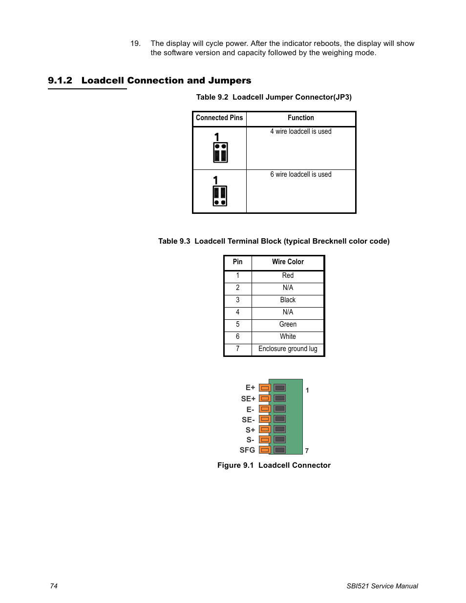
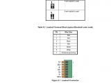
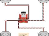
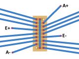
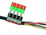
2 loadcell connection and jumpers loadcell connection and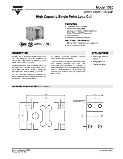
model 1320 high capacity single point load cell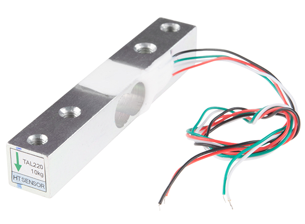
getting started with load cells learn sparkfun com
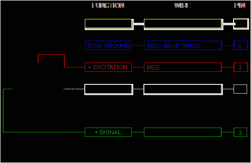
load cell cabling marco iw nl 4 wire 6 wire load cells a load cell may have a cable with four or six wires a six wire cable besides having excitation and signal lines also has and sense lines it is a common misconception that the possibility to sense the actual voltage at the load cell is the only difference between 4 wire and 6 wire load cells 6 wire load cell wiring engine diagram and wiring diagram this is a image galleries about 6 wire load cell wiring you can also find other images like wiring diagram parts diagram replacement parts electrical diagram repair manuals engine diagram engine scheme wiring harness fuse box vacuum diagram timing belt timing chain brakes diagram transmission diagram and engine problems hbm load cell wiring diagram wiring color code diagram for transducer techniques load cells available online for download or viewing come checkout other online services depending on the model the load cells may have a cable with 4 or 6 wires plus the screen the 6 wire models in addition to having the terminals of power 6 wire load cell diagram chanish org 6 wire load cell diagram april 10 2019 technical information www aandd jp load cell fault finding www groupfourtransducers com six wire load cell connection www utilcell com amana thermostat troubleshooting motorguide brute 67 wiring diagram how to wire a 6 pin trailer plug red electrical outlet top outlet not working how to wire multiple lights together black fan with light a practical guide to wiring the load cell and amplifier wiring the amp to the dataq unit any suitable analog to digital converter may be used to convert the analog output of the load cell amplifier to a digital signal dataq com sells affordable units that work admirably for data collection of hobby rocket motors performance for example di 145 di 149 and di 155 units are economical choices load cell color codes by manufacturer manufacturer models excitation excitation signal signal shield sense sense a d engineering red white green blue yellow allegany green black 6 how to use load cells 6 how to use load cells load cells should be selected after considering the following points 1 loading conditions determine the loading conditions of the load cell ten sion compression bending etc that best suit the getting started with load cells learn sparkfun com most strain gauge load cells work in very similar ways but may vary in size material and mechanical setup which can lead to each cell having different max loads and sensitivities that they can handle for a few possible load cell mechanical setups check out the hookup guide with the load cell setup troubleshooting load cell bridge circuit and wiring troubleshooting load cell bridge circuit and wiring connections damages in wire connection are one of the most common faults of a load cell troubleshooting load cell bridge circuit is the basic checkings before contacting support or sending it for service the following steps are suitable for troubleshooting s load cell troubleshooting the diagram below represents a proposed sequence for testing load cells after a particular system malfunction isolate the fault location by moving a relatively small deadweight over each load cell or by disconnecting load cell by load cell test 1 zero balance the zero balance is defined as the load cell output in a no load situation therefore all weight including dead load has
