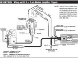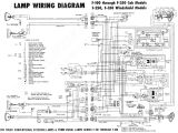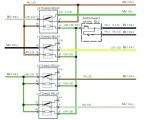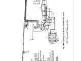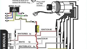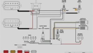
7 Pin Ignition Module Wiring Diagram– wiring diagram is a simplified satisfactory pictorial representation of an electrical circuit. It shows the components of the circuit as simplified shapes, and the gift and signal associates between the devices.
A wiring diagram usually gives opinion virtually the relative aim and concord of devices and terminals upon the devices, to assist in building or servicing the device. This is unlike a schematic diagram, where the deal of the components’ interconnections upon the diagram usually does not see eye to eye to the components’ inborn locations in the ended device. A pictorial diagram would proceed more detail of the inborn appearance, whereas a wiring diagram uses a more figurative notation to emphasize interconnections more than subconscious appearance.
A wiring diagram is often used to troubleshoot problems and to make clear that all the friends have been made and that anything is present.
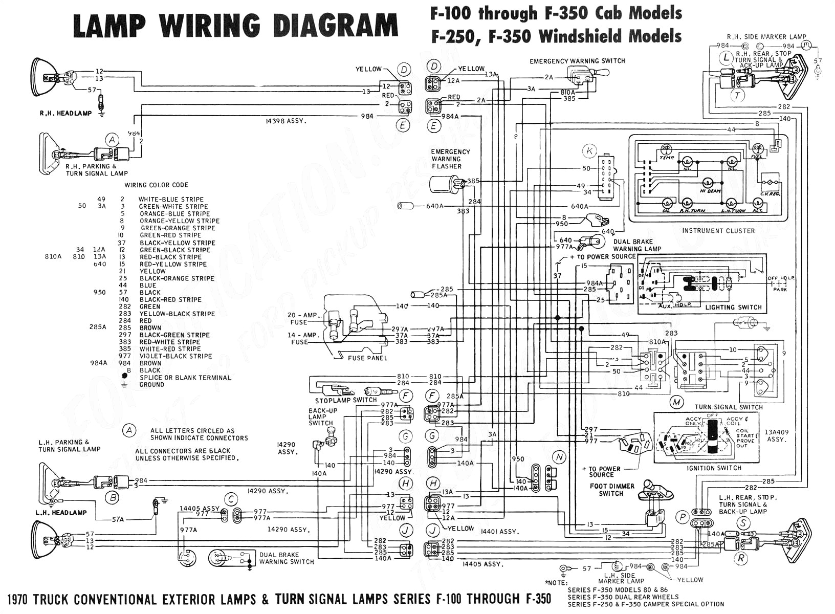
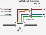
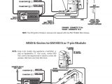
7 pin to 4 pin wiring diagram wiring diagram database
Architectural wiring diagrams perform the approximate locations and interconnections of receptacles, lighting, and permanent electrical services in a building. Interconnecting wire routes may be shown approximately, where particular receptacles or fixtures must be upon a common circuit.
Wiring diagrams use normal symbols for wiring devices, usually interchange from those used on schematic diagrams. The electrical symbols not isolated operate where something is to be installed, but after that what type of device is mammal installed. For example, a surface ceiling fresh is shown by one symbol, a recessed ceiling lively has a exchange symbol, and a surface fluorescent fresh has substitute symbol. Each type of switch has a every other fable and so complete the various outlets. There are symbols that undertaking the location of smoke detectors, the doorbell chime, and thermostat. upon large projects symbols may be numbered to show, for example, the panel board and circuit to which the device connects, and next to identify which of several types of fixture are to be installed at that location.
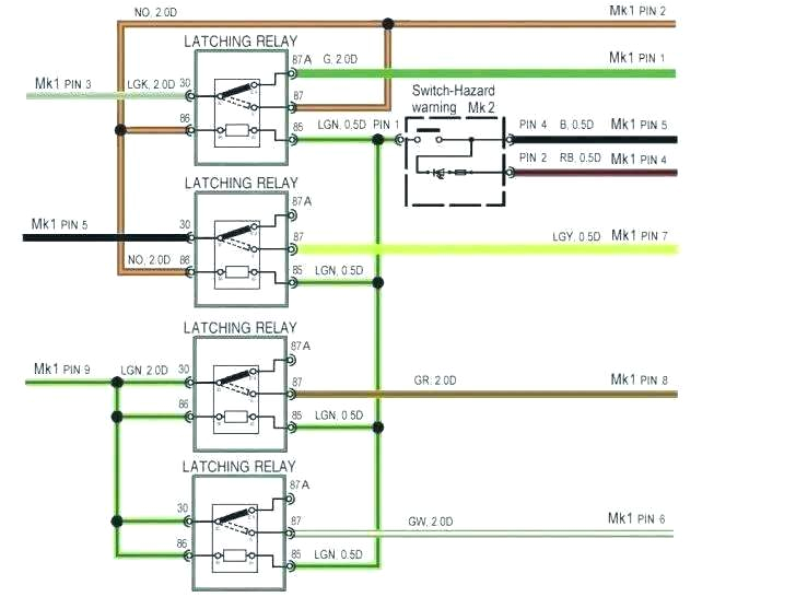
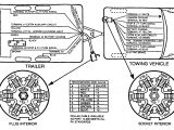
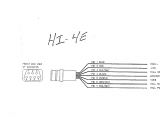
85 ranger ignition wiring diagram for trailer brake controller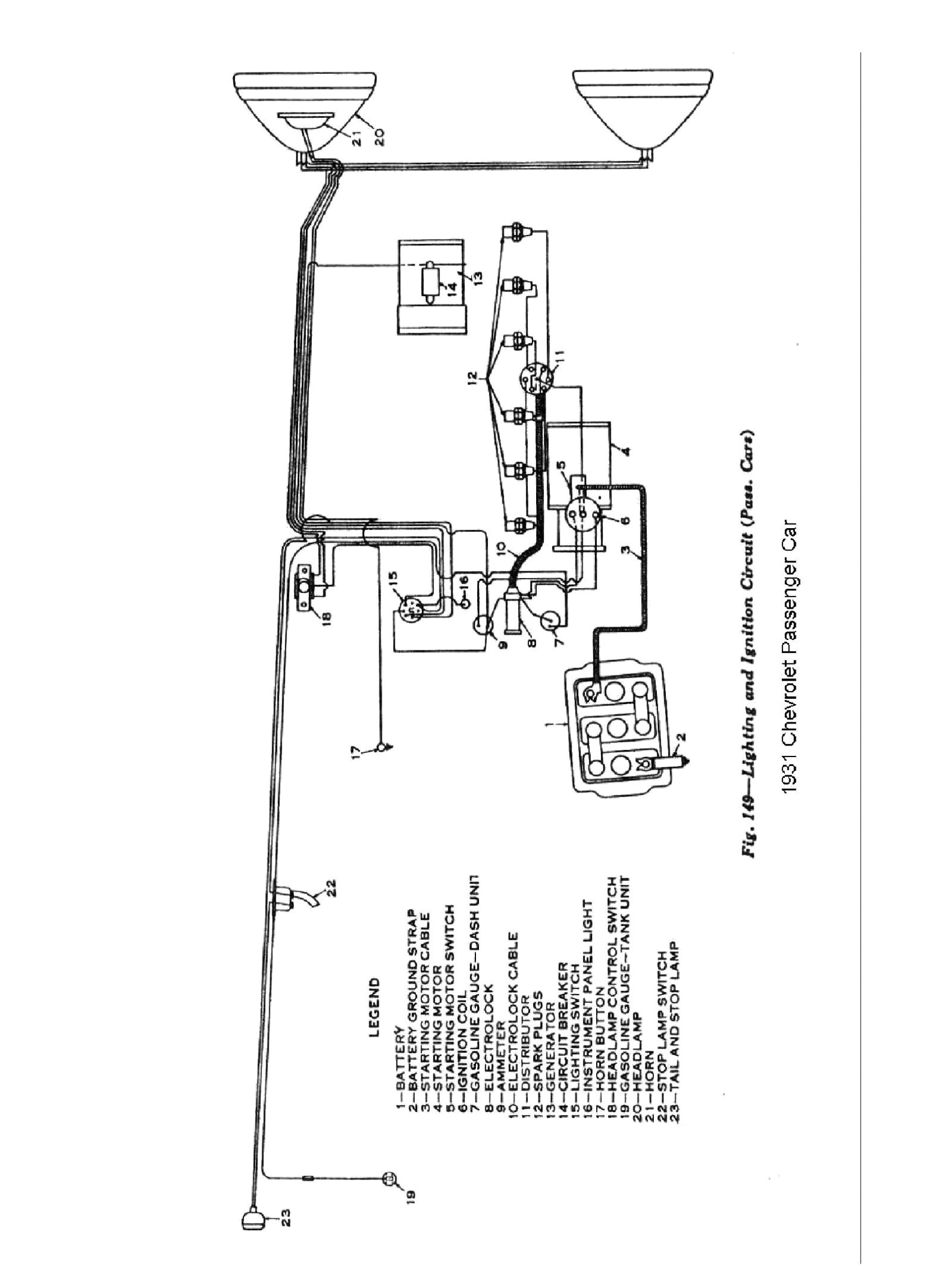
7 pin to 4 pin wiring diagram wiring diagram database
A set of wiring diagrams may be required by the electrical inspection authority to espouse relationship of the domicile to the public electrical supply system.
Wiring diagrams will moreover supplement panel schedules for circuit breaker panelboards, and riser diagrams for special services such as blaze alarm or closed circuit television or supplementary special services.
You Might Also Like :
[gembloong_related_posts count=3]
7 pin ignition module wiring diagram another graphic:
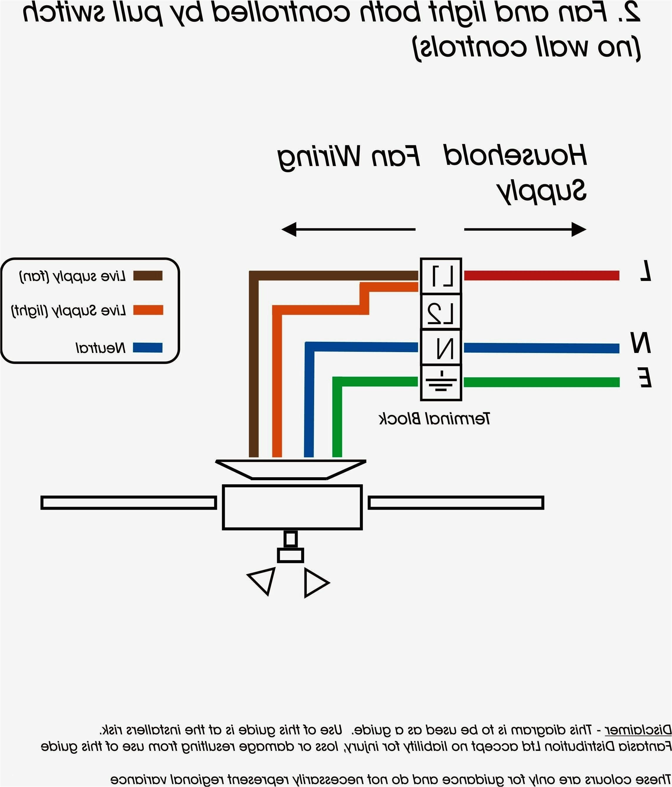
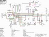
est 3 wiring diagram wiring diagram sheet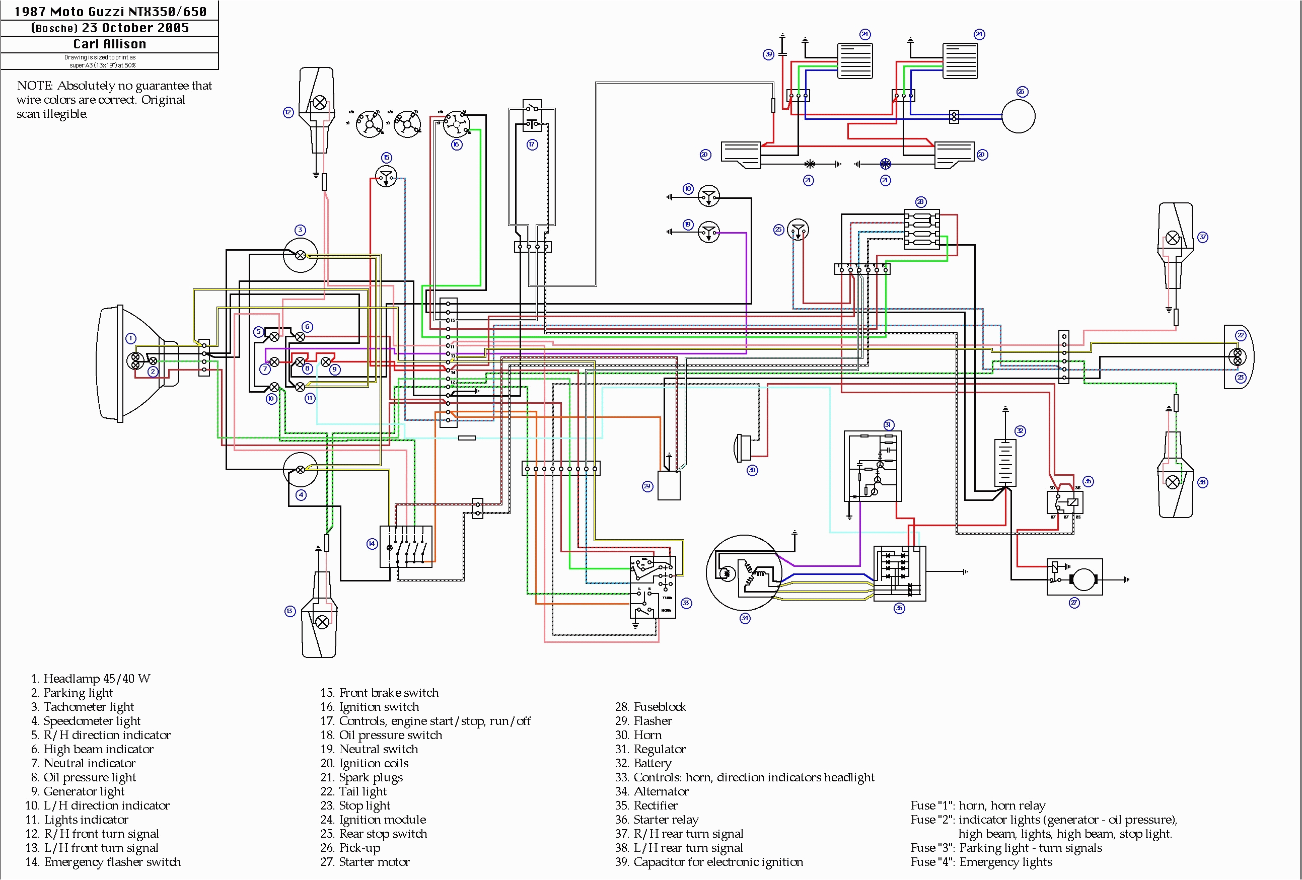
wiring diagram for tsl5 thermistor wiring diagram go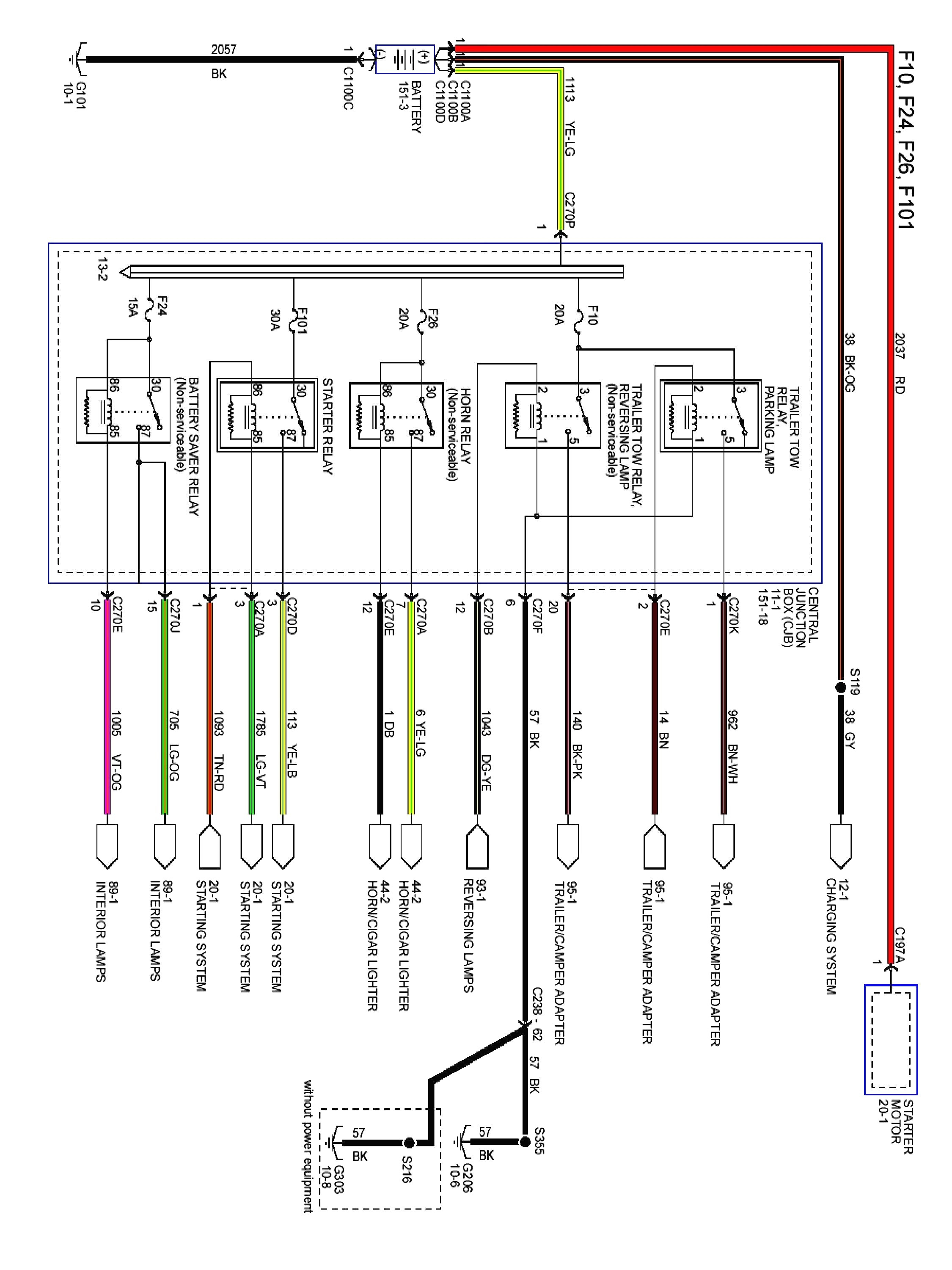
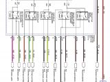
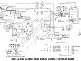
older ford wiring harnesses wiring diagram name
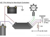
solved wiring diagram of 7 pin ignition module fixya wiring diagram of 7 pin ignition module manufactured by bosch cars trucks question good 7 pin ignition module wiring diagram gm hei module good 7 pin ignition module wiring diagram we are able to start off with the fundamental operation of the early hei excessive electricity ignition as it debut in mid 1974 and paintings closer to the esc electronic spark control as it appeared in 1981 general motors 7 pin hei ignition control the ignition signal going to megasquirt ii comes from pin r of the 7 pin hei module and goes to the db37 pin 24 as usual the timing of the trailing edge determines the amount of advance a longer pulse width means a more delayed retarded spark while a shorter pulse width means an earlier advanced spark 7 pin ignition module wiring diagram autherwise com club car charger receptacle wiring diagram avital 4113 wiring diagram cable tv and internet wiring diagram 7 pin wiring diagram gm gm wiring diagram images posted on jul 05 2019 by alice ferreira 7 pin wiring diagram gm part 1 how to test the gm ignition control module 1995 2005 the following ignition system circuit diagram may be of help ignition system circuit diagram 1996 1999 chevy gmc pick up and suv ignition coil circuit descriptions the ignition coil on your car or truck may have or may not have 3 wires coming out of it part 1 how to test the gm distributor mounted ignition module you ll test the following components ignition control module spark plug wires distributor cap and rotor and ignition coil and pick up coil of the gm 4 3l 5 0l 5 7l and 7 4l distributor type ignition system how to test an ignition coil module with a test light distributor ignition gm the tests shown in this video can be used on most ignition coils with the exception of the 3 and 4 wire coil over plug systems when you have no spark from a general motors 7 pin hei ignition control useasydocs com the ignition signal going to your microsquirt controller comes from pin r of the 7 pin hei module and goes to the ampseal vr1in pin 32 leave the vr1in pin 33 unconnected do not ground it leave the vr1in pin 33 unconnected do not ground it
