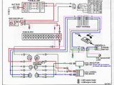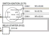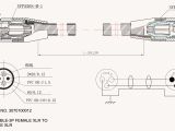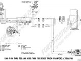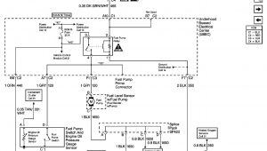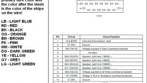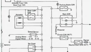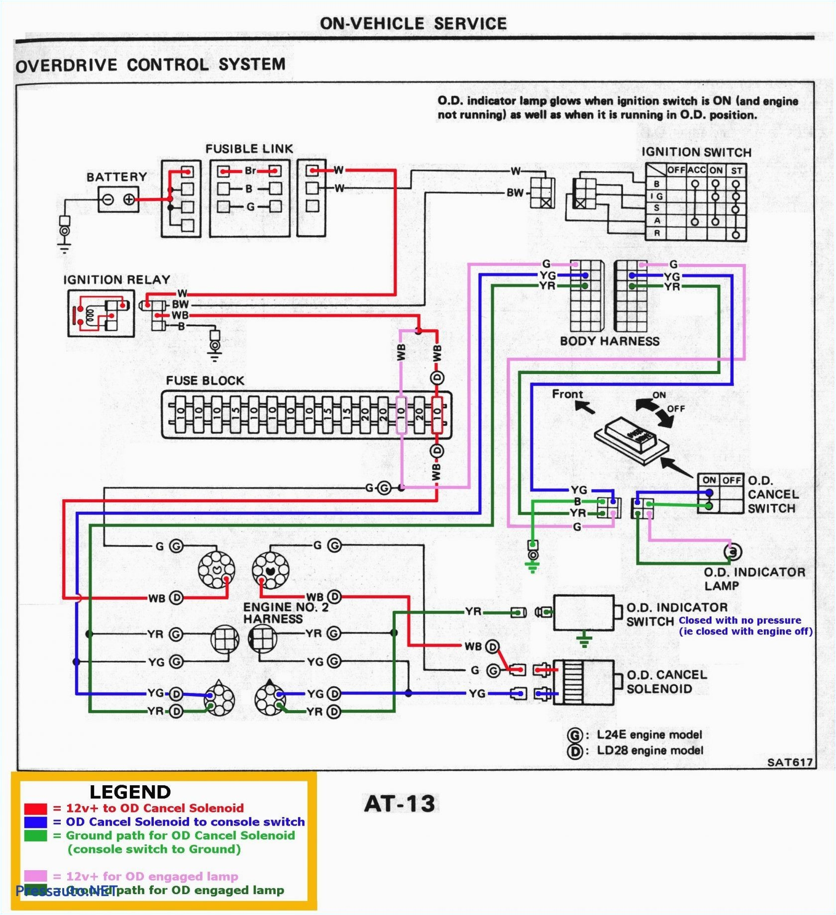
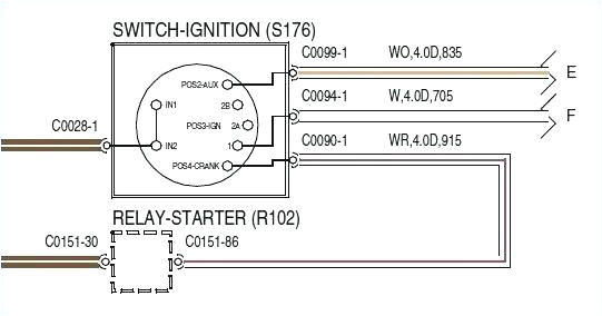
Marine Voltage Regulator Wiring Diagram– wiring diagram is a simplified suitable pictorial representation of an electrical circuit. It shows the components of the circuit as simplified shapes, and the skill and signal connections amongst the devices.
A wiring diagram usually gives counsel nearly the relative slope and settlement of devices and terminals upon the devices, to assist in building or servicing the device. This is unlike a schematic diagram, where the deal of the components’ interconnections on the diagram usually does not match to the components’ inborn locations in the finished device. A pictorial diagram would feat more detail of the instinctive appearance, whereas a wiring diagram uses a more figurative notation to bring out interconnections on top of living thing appearance.
A wiring diagram is often used to troubleshoot problems and to create sure that all the associates have been made and that anything is present.
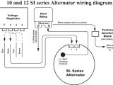
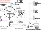
prestolite wiring diagram caribbeancruiseship org
Architectural wiring diagrams enactment the approximate locations and interconnections of receptacles, lighting, and enduring electrical services in a building. Interconnecting wire routes may be shown approximately, where particular receptacles or fixtures must be on a common circuit.
Wiring diagrams use conventional symbols for wiring devices, usually alternative from those used upon schematic diagrams. The electrical symbols not forlorn conduct yourself where something is to be installed, but in addition to what type of device is being installed. For example, a surface ceiling open is shown by one symbol, a recessed ceiling lively has a substitute symbol, and a surface fluorescent vivacious has choice symbol. Each type of switch has a interchange parable and suitably complete the various outlets. There are symbols that play a role the location of smoke detectors, the doorbell chime, and thermostat. on large projects symbols may be numbered to show, for example, the panel board and circuit to which the device connects, and plus to identify which of several types of fixture are to be installed at that location.
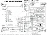
318 engine wiring diagram wiring diagram page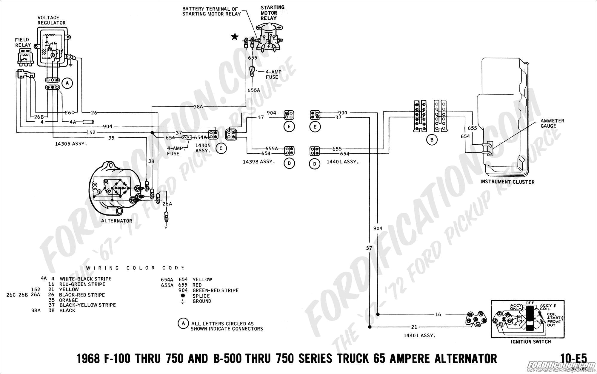
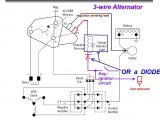
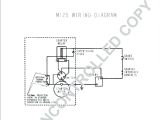
late motorola style alternator wiring book diagram schema
A set of wiring diagrams may be required by the electrical inspection authority to approve connection of the address to the public electrical supply system.
Wiring diagrams will afterward include panel schedules for circuit breaker panelboards, and riser diagrams for special services such as blaze alarm or closed circuit television or extra special services.
You Might Also Like :
[gembloong_related_posts count=3]
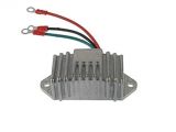
marine voltage regulator wiring diagram another impression:
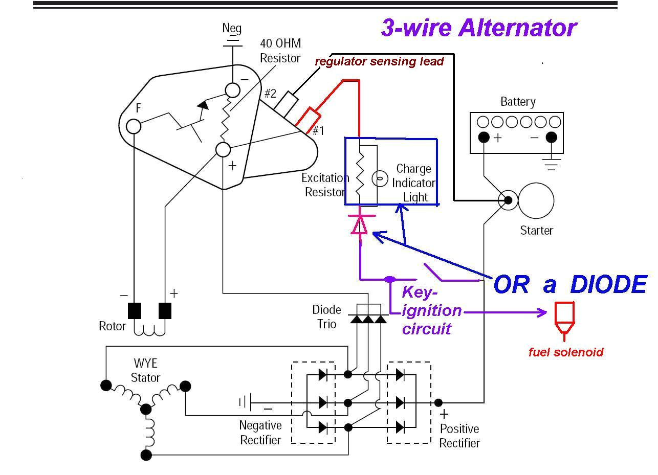
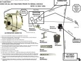
diesel 3 wire alternator diagram wiring diagram center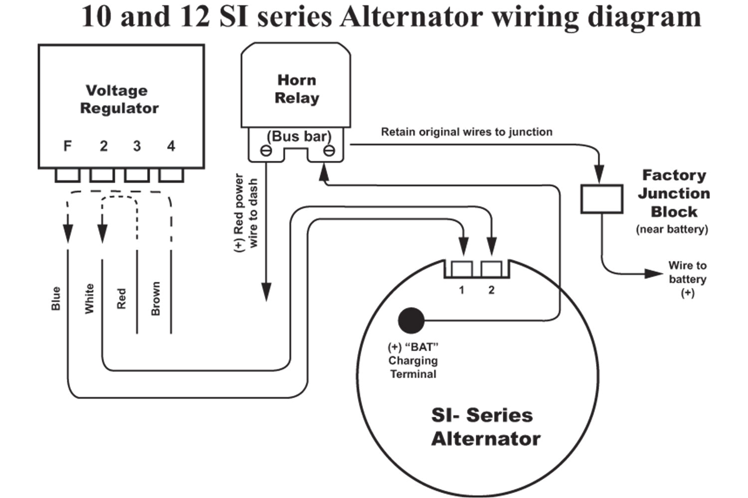
late motorola style alternator wiring book diagram schema
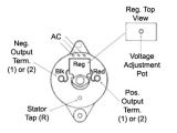
prestolite leece neville
charging system wiring diagram charging system wiring diagram amazon printed books https www createspace com 3623931 amazon kindle edition http www amazon com automotive elec marine voltage regulator wiring best free wiring diagram marine voltage regulator wiring thank you for visiting our site this is images about marine voltage regulator wiring posted by ella brouillard in marine category on jul 12 2019 12 volt alternator installation operation manual 7 if a new regulator is being installed along with the alternator complete its wiring installation according to the instructions includ ed with your regulator voltage regulator circuit with schematic diagrams well this is a collection of voltage regulator circuits using the lm317 ic which is an adjustable voltage regulator lm317 is a three terminal adjustable regulator from national semiconductors and it s input can range up to 40 volts the output voltage can be adjusted from 1 2 v to 37 v now this article is a collection of 4 circuits using lm317 programming a balmar external voltage regulator marine field potential for a balmar regulator is battery voltage sensed voltage minus about a 0 4v to 0 5v drop across the regulator fet s so a battery voltage of 13 5v during bulk charging as voltage is climbing results in a field potential of about 13 0v to 13 1v 12 volt electrical systems boattech boatus 12 volt electrical systems the majority of boats on the water today depend on electricity to some degree unfortunately too many of those boats are operating with inadequate and poorly installed electrical systems alternator wiring marine engine parts many alternators require ignition voltage to initiate charging you must verify that all required connections are connected to the proper terminal and have the correct voltage in order for the alternator to operate properly how to test a regulator rectifier here i am only testing the regulator portion of a common regulator rectifier want more check out the blog by visiting the website below if you want to dive even deeper with any questions on 24 volt alternator installation operation manual harness as indicated in wiring diagram included on page 12 the alternator s positive and ground the alternator s positive and ground cables should be sized according to the chart on page 3
