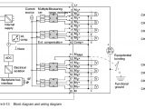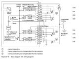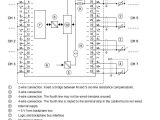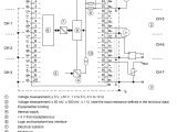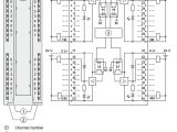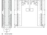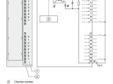
6es7 331 7pf01 0ab0 Wiring Diagram– wiring diagram is a simplified welcome pictorial representation of an electrical circuit. It shows the components of the circuit as simplified shapes, and the gift and signal connections in the middle of the devices.
A wiring diagram usually gives opinion very nearly the relative point of view and deal of devices and terminals upon the devices, to encourage in building or servicing the device. This is unlike a schematic diagram, where the covenant of the components’ interconnections upon the diagram usually does not reach a decision to the components’ being locations in the finished device. A pictorial diagram would play more detail of the living thing appearance, whereas a wiring diagram uses a more figurative notation to put emphasis on interconnections higher than subconscious appearance.
A wiring diagram is often used to troubleshoot problems and to create definite that every the links have been made and that all is present.
profibus connector a siemens s7 300
Architectural wiring diagrams decree the approximate locations and interconnections of receptacles, lighting, and steadfast electrical facilities in a building. Interconnecting wire routes may be shown approximately, where particular receptacles or fixtures must be on a common circuit.
Wiring diagrams use within acceptable limits symbols for wiring devices, usually interchange from those used on schematic diagrams. The electrical symbols not single-handedly do something where something is to be installed, but along with what type of device is monster installed. For example, a surface ceiling blithe is shown by one symbol, a recessed ceiling roomy has a every other symbol, and a surface fluorescent spacious has unconventional symbol. Each type of switch has a oscillate story and as a result attain the various outlets. There are symbols that produce an effect the location of smoke detectors, the doorbell chime, and thermostat. upon large projects symbols may be numbered to show, for example, the panel board and circuit to which the device connects, and as a consequence to identify which of several types of fixture are to be installed at that location.
profibus connector a siemens s7 300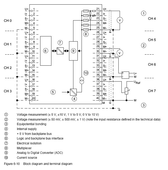
profibus connector a siemens s7 300
A set of wiring diagrams may be required by the electrical inspection authority to assume relationship of the quarters to the public electrical supply system.
Wiring diagrams will also total panel schedules for circuit breaker panelboards, and riser diagrams for special facilities such as flare alarm or closed circuit television or extra special services.
You Might Also Like :
- 2007 Honda Pilot Radio Wiring Diagram
- Cutler Hammer Shunt Trip Breaker Wiring Diagram
- Cat 5 Wiring Diagram Pdf
6es7 331 7pf01 0ab0 wiring diagram another picture:
profibus connector a siemens s7 300
profibus connector a siemens s7 300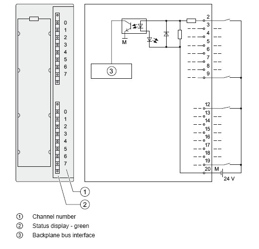
profibus connector a siemens s7 300
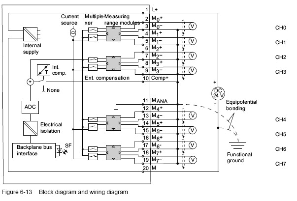
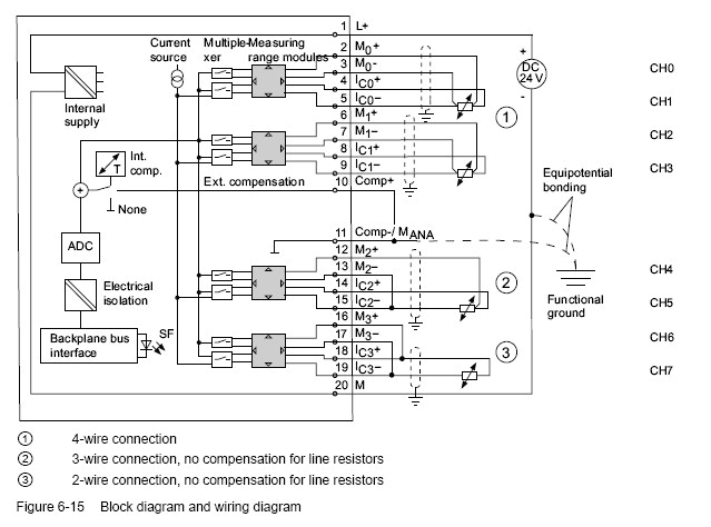
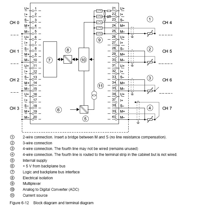
manual for 6es7 331 7pf01 0ab0 8 ai rtd card entries manual for 6es7 331 7pf01 0ab0 8 ai rtd card created by dufour at 6 8 2012 1 39 am 1 replies rating 0 hello i have been searching for the manual for 2 days and have been unsuccessful i am hoping to find a wiring diagram so i can verify the installation best regards greg dufour nike inc suggestion to thank quote answer 6 8 2012 3 40 am rate 0 dchartier grandmaster expert 6es7331 7pf01 0ab0 industry support siemens siemens industry online support siemens ag view product details industry mall siemens ww 6es7331 7pf01 0ab0 product description simatic s7 300 analog input sm 331 isolated 2 3 4 wire 8 ai resistor pt100 200 1000 ni100 120 200 500 1000 cu10 characteristics according to gost 16 internal 24 bit 50ms 1x 40 pole product family sm 331 analog input modules product lifecycle plm pm300 active product price data price group 231 list price show prices customer price 6es7331 7kf02 0ab0 ai wiring entries forum industry hi new to siemens so please be gentle currently trying to commission a siemnes plc and analogue card as above can some please tell me if the wiring diagram is correct we have 5 2 wire 4 20ma signals and the rest of the inputs are spare tia mark sm331 8ai 13bit 6es7331 1kf02 0ab0 industry support 6es7331 1kf02 0ab0 sm331 8ai 13bit simatic s7 300 analog input sm 331 isolated 8 ai resolution 13 bits u i resistor pt100 ni100 ni1000 lg ni1000 ptc kty 66 ms conversion time 1x 40 pole siemens industry online support siemens ag view industry online support product support internet internet register log in industry online support international international english product data sheet 6es7331 7pf01 0ab0 cdn plc trade com product data sheet 6es7331 7pf01 0ab0 simatic s7 300 analog input sm 331 opt isol 2 3 4 wire 8ai resistance pt100 200 1000 ni100 120 200 500 1000 cu10 plus characteristics according to gost standard 16 intern 24 bit 50ms 1 x 40 pin supply voltage load voltage l rated value dc 24 v reverse polarity protection yes input current from load voltage l without load max 240 ma produktdetails industry mall siemens ww 6es7331 7tf01 0ab0 artikelbeschreibung simatic dp hart analogeingabe sm 331 8ae 0 4 20ma hart fur et200m mit im153 2 1 x 20 polig funktionen fw update hart nebenvariablen redundanz lokaler diagnosepuffer mit zeitstempelung produktfamilie analogeingabebaugruppe mit hart produktstatus pm300 aktives produkt preisinformationen preisgruppe 280 einzelpreis preise anzeigen produktdetails industry mall siemens de 6es7331 7pf01 0ab0 artikelbeschreibung simatic s7 300 analogeingabe sm 331 pot getr 2 3 4 draht 8ae widerstand pt100 200 1000 ni100 120 200 500 1000 cu10 kennlinien nach gost 16 intern 24 bit 50ms 1x 40 polig produktfamilie analogeingabe sm 331 produktstatus pm300 aktives produkt preisinformationen preisgruppe stammhaus preisgruppe 231 231 einzelpreis preise 6 7 analog input module sm 331 ai 8 x 12 bit 6es7331 6 7 analog input module sm 331 ai 8 x 12 bit 6es7331 7kf02 0ab0 s7 300 module data manual 02 2013 a5e00105505 08 371 terminal assignment the diagrams below show various wiring options the input impedance depends on the setting of the measuring range module see table measurement types and ranges wiring voltage measurement 9 9 9 9 9 9 6es7331 7kf02 0ab0 manual linkedin slideshare analog modules 6 7 analog input module sm 331 ai 8 x 12 bit 6es7331 7kf02 0ab0 s7 300 module data 372 manual 02 2013 a5e00105505 08 wiring 2 wire and 4 wire transducers for current measurement figure 6 14 block diagram and wiring diagram note the interconnection between mana and m terminals 11 13 15 17 19 is not required when using grounded 4 wire transducers with non isolated supply
