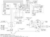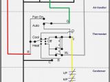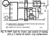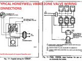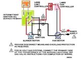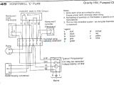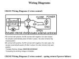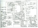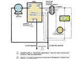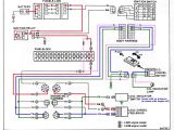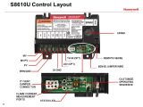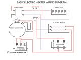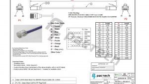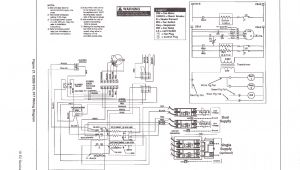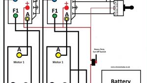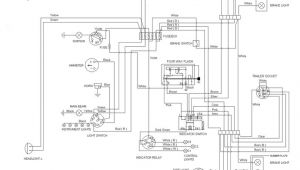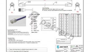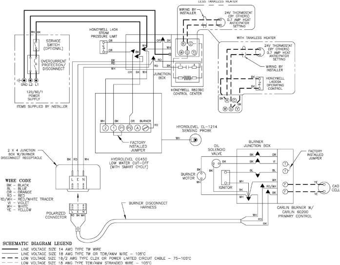
Honeywell Burner Control Wiring Diagram– wiring diagram is a simplified customary pictorial representation of an electrical circuit. It shows the components of the circuit as simplified shapes, and the skill and signal connections amid the devices.
A wiring diagram usually gives information approximately the relative approach and understanding of devices and terminals upon the devices, to support in building or servicing the device. This is unlike a schematic diagram, where the deal of the components’ interconnections on the diagram usually does not allow to the components’ visceral locations in the finished device. A pictorial diagram would law more detail of the subconscious appearance, whereas a wiring diagram uses a more figurative notation to play up interconnections more than being appearance.
A wiring diagram is often used to troubleshoot problems and to create distinct that all the contacts have been made and that all is present.
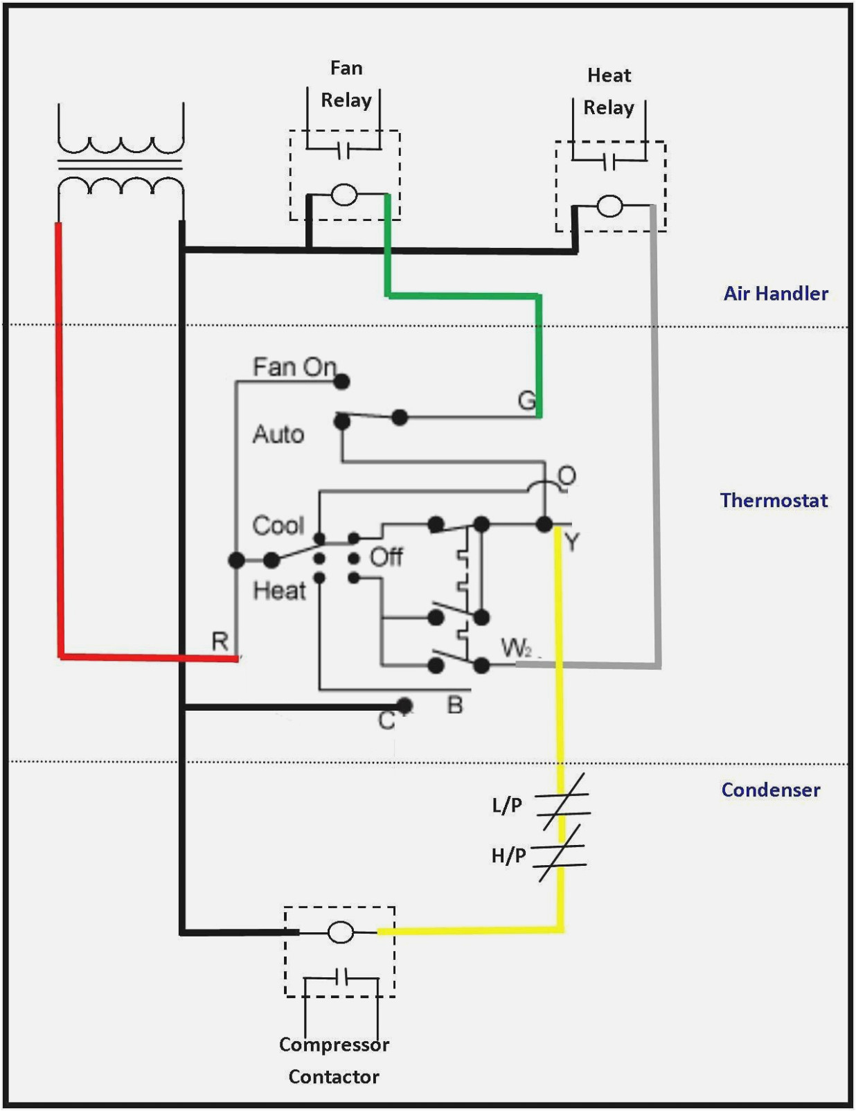
oil wiring diagram blog wiring diagram
Architectural wiring diagrams be active the approximate locations and interconnections of receptacles, lighting, and permanent electrical services in a building. Interconnecting wire routes may be shown approximately, where particular receptacles or fixtures must be upon a common circuit.
Wiring diagrams use agreeable symbols for wiring devices, usually exchange from those used on schematic diagrams. The electrical symbols not isolated behave where something is to be installed, but after that what type of device is physical installed. For example, a surface ceiling buoyant is shown by one symbol, a recessed ceiling blithe has a vary symbol, and a surface fluorescent lighthearted has substitute symbol. Each type of switch has a swing symbol and thus realize the various outlets. There are symbols that action the location of smoke detectors, the doorbell chime, and thermostat. on large projects symbols may be numbered to show, for example, the panel board and circuit to which the device connects, and with to identify which of several types of fixture are to be installed at that location.
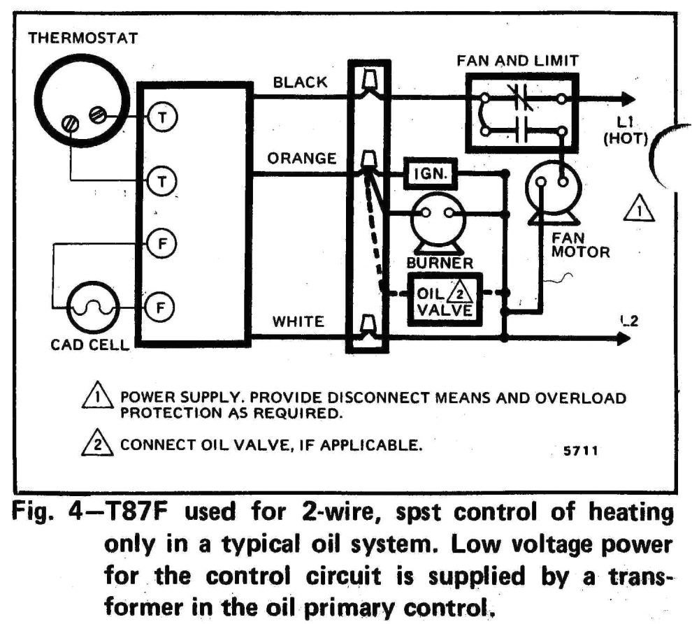
oil wiring diagram blog wiring diagram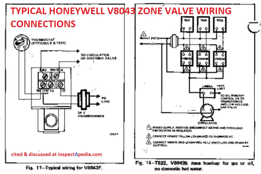
aquastats diagnosis repair setting wiring heating
A set of wiring diagrams may be required by the electrical inspection authority to take up attachment of the dwelling to the public electrical supply system.
Wiring diagrams will as a consequence enhance panel schedules for circuit breaker panelboards, and riser diagrams for special services such as blaze alarm or closed circuit television or new special services.
You Might Also Like :
[gembloong_related_posts count=3]
honeywell burner control wiring diagram another graphic:
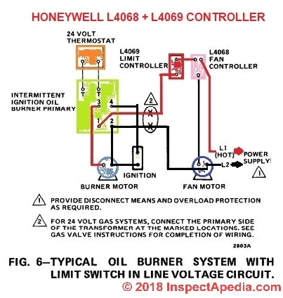
fan limit wiring diagram pro wiring diagram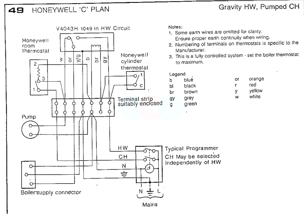
honeywell oil furnace wiring diagram blog wiring diagram
wrg 4671 wiring diagram for actuator
honeywell burner control wiring diagram gallery wiring honeywell burner control wiring diagram just what s wiring diagram a wiring diagram is a kind of schematic which makes use of abstract photographic symbols to reveal all the interconnections of parts in a system wiring diagrams honeywell home heating controls our wiring diagrams section details a selection of key wiring diagrams focused around typical sundial s and y plans wiring diagrams contains all the essential wiring diagrams across our range of heating controls click the icon or the document title to download the pdf downloads heating controls wiring guide issue 17 v4073a y plan how a mid position valve operates within a y plan heating honeywell burner control wiring diagram free wiring diagram honeywell burner control wiring diagram collections of 98 honda civic fuse diagram http autowiringdiagram 2011 honeywell burner control wiring diagram honeywell relay wiring diagram save taco pump wiring diagram lovely oil burner wiring diagram to 2ppzo5t at control boiler wiring conversion iwring diagrams for rm7800 rm7840 b m l z rev 2 95 c honeywell inc 1995 1 65 0100 2 caution 1 installer must be a trained experienced flame safeguard control service technician 2 disconnect power supply before beginning installation to prevent electrical shock and equipment damage more than one power supply disconnect may be involved 3 all wiring must comply with applicable local electrical codes 65 0125 conversion wiring diagrams for rm7895 honeywell and programmers to rm7895 microprocessor based integrated burner control conversion wiring diagrams for rm7895 found to comply with the limits for a class b computing device of part 15 of fcc rules which are designed to provide reasonable protection against such interfer ence when operated in a commercial environment operation of this equipment in a residential area may cause interference 65 0126 7800 series rm7890a b c relay module honeywell 7800 series rm7890a b c relay module the honeywell rm7890 is a microprocessor based integrated burner control for automatically fired gas oil or combination fuel single burner appli cations the rm7890 consists of the relay module subbase and amplifier are required to complete the system options include keyboard display module personal computer interface data controlbus module remote ra890f flame safeguard primary control honeywell able wiring enclosure low voltage control circuit t t 0 3a note allowable inrush can be up to ten times the pilot duty rating example pilot duty rating 25 va at 120v running current is 25 0 21a maximum allowable inrush is 10 times 0 21 2 1a maximum power interruption 12 milliseconds longer inter ruption causes 1k to drop out burner shuts down after a short delay for 68 0113 1 r4184d r8184g n protectorelay oil burner controls protectorelay oil burner controls r4184d r8184g n d t rev 5 91 form number 68 0113 1 c honeywell inc 1991 specifications important the specifications given in this publication do not include normal manufacturing tolerances therefore this may not match the listed specifications exactly also this product is tested and calibrated under closely controlled conditions and some minor yellow heat burner controller setup yellow heat vegetable oil burners can be installed in boiler or furnaces here is the simple programming that should be done for optimal performance 5 minut oil burner controller replaced honeywell i am a dentist by trade but have learned so much on yt especially steve lav s channel to which im a patreon i can either call and wait or if its an easy fix do it myself this is what i came
