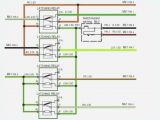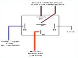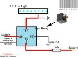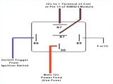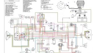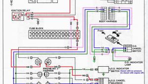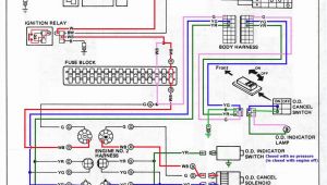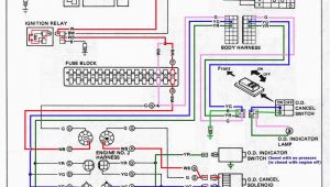
5 Terminal Relay Wiring Diagram– wiring diagram is a simplified suitable pictorial representation of an electrical circuit. It shows the components of the circuit as simplified shapes, and the capacity and signal contacts between the devices.
A wiring diagram usually gives recommendation approximately the relative twist and bargain of devices and terminals on the devices, to support in building or servicing the device. This is unlike a schematic diagram, where the accord of the components’ interconnections on the diagram usually does not come to an agreement to the components’ swine locations in the over and done with device. A pictorial diagram would fake more detail of the visceral appearance, whereas a wiring diagram uses a more figurative notation to put emphasis on interconnections more than instinctive appearance.
A wiring diagram is often used to troubleshoot problems and to make determined that every the connections have been made and that whatever is present.
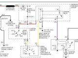
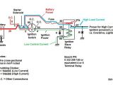
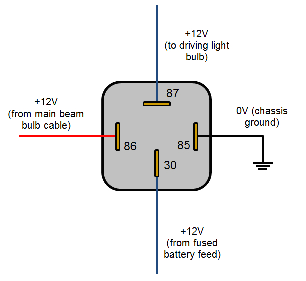
interally relay wiring diagram automotive electrical
Architectural wiring diagrams produce an effect the approximate locations and interconnections of receptacles, lighting, and remaining electrical facilities in a building. Interconnecting wire routes may be shown approximately, where particular receptacles or fixtures must be on a common circuit.
Wiring diagrams use welcome symbols for wiring devices, usually every second from those used on schematic diagrams. The electrical symbols not unaided feat where something is to be installed, but along with what type of device is mammal installed. For example, a surface ceiling lively is shown by one symbol, a recessed ceiling vivacious has a exchange symbol, and a surface fluorescent vivacious has other symbol. Each type of switch has a substitute story and hence complete the various outlets. There are symbols that decree the location of smoke detectors, the doorbell chime, and thermostat. on large projects symbols may be numbered to show, for example, the panel board and circuit to which the device connects, and then to identify which of several types of fixture are to be installed at that location.
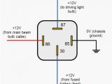
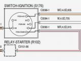
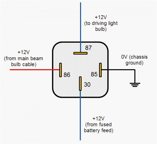
automotive relay diagram diagram circuit relay 5 pin
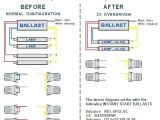
tl 1947 relay circuit 5 pin
A set of wiring diagrams may be required by the electrical inspection authority to accept association of the habitat to the public electrical supply system.
Wiring diagrams will with include panel schedules for circuit breaker panelboards, and riser diagrams for special facilities such as blaze alarm or closed circuit television or new special services.
You Might Also Like :
[gembloong_related_posts count=3]
5 terminal relay wiring diagram another image:
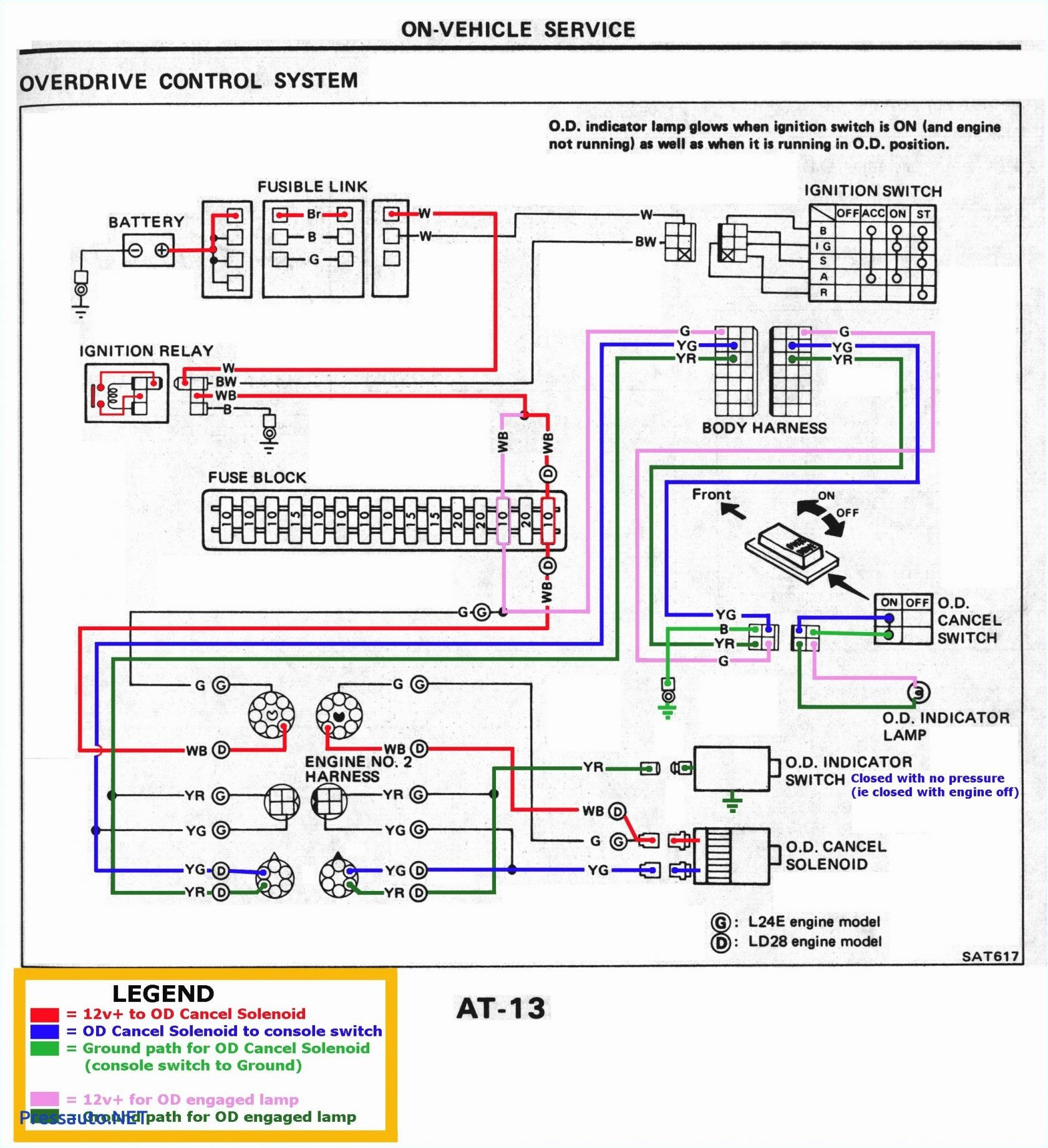
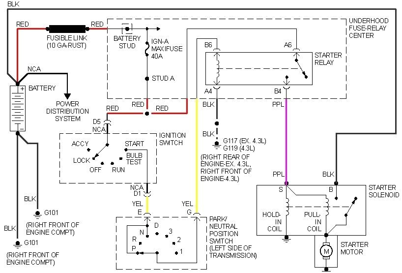
gm relay wiring diagram fokus dego25 vdstappen loonen nl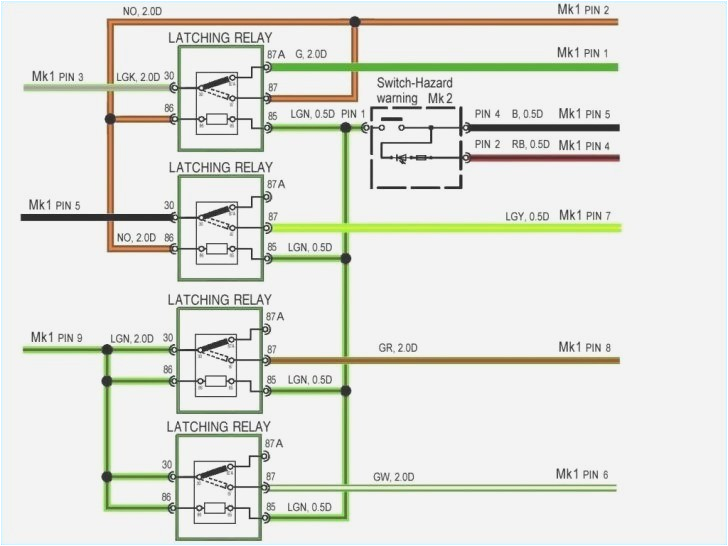
xr 7416 5 pin latching relay wiring diagram free diagram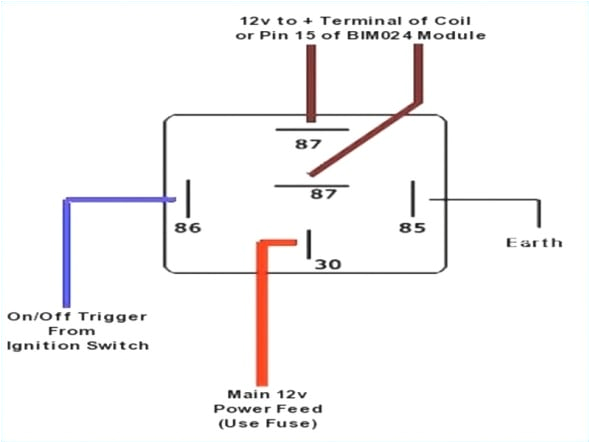
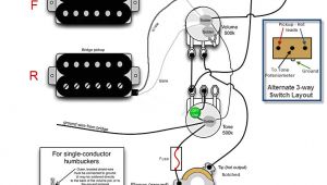
5 post relay wiring diagram diagram base website wiring
how a 5 pin relay works the easiest latching relay circuit to understand ever both theory and practical explained duration 12 30 mrmattandmrchay 493 598 views how to wire a 4 or 5 pin relay in this video i show you how to wire a 12 volt automotive bosch style relay this video covers both 4 and 5 pin 12vdc relays best connections 12voltwire com patreon https www patreon com understanding relays wiring diagrams swe check 5 pin relay 5 pin relays provide 2 pins 85 86 to control the coil and 3 pins 30 87 87a which switch power between two circuits they have both normally open and normally closed connection pins when the coil is activated power will be switched from the normally closed pin to the normally open pin 5 terminal relay wiring diagram wiring source 5 terminal relay wiring diagram welcome thank you for visiting this simple website we are trying to improve this website the website is in the development stage support from you in any form really helps us we really appreciate that we will share this website for you articles and images of wiring diagrams engine schemes engine problems engine diagrams transmission diagrams 5 terminal relay wiring diagram engine diagram and 5 terminal relay wiring diagram this is a image galleries about 5 terminal relay wiring diagram you can also find other images like wiring diagram parts diagram replacement parts electrical diagram repair manuals engine diagram engine scheme wiring harness fuse box vacuum diagram timing belt timing chain brakes diagram transmission diagram and engine problems interpreting results of a 5 pin relay test purkeys interpreting results of a 5 pin relay test purkeys 4 or 5 pin relay with or without a diagram duration 14 11 ratchets and wrenches 1 017 700 views 14 11 how to use a relay as a kill 5 pin bosch relay wiring diagram wiring diagram and description 5 pin spdt relay wiring diagram 12 volt 5 pin relay diagram wiring for 5 pin bosch relay wiring diagram image size 650 x 650 px image source www online led store com truly we have been realized that 5 pin bosch relay wiring diagram is being just about the most popular subject at this time identify terminal pins of a relay without reference to relays that normally used in electronic circuits are spdt and dpdt types due to their flexibility in controlling circuit switching in the next section a demonstration on identifying the pins of a relay from spdt or dpdt type without referring to its datasheet will be illustrated a 5 pins type relay automotive relay guide 12 volt planet the terminal widths used on 4 and 5 pin relays are almost always 6 3mm wide however some more specialist relays can have terminal widths of 2 8mm 4 8mm and 9 5mm the 9 5mm wide terminals tend to be used for higher power applications such as for starter motor solenoid activation and the smaller terminals tend to be used for electronics signalling where only very low currents are required 12 volt relay wiring diagram free wiring diagram name 12 volt relay wiring diagram bosch relay wiring diagram 5 pole fresh 5 pin relay wiring diagram inspirational pin relay wiring file type jpg source bellbrooktimes com size 261 54 kb dimension 1510 x 1283 assortment of 12 volt relay wiring diagram click on the image to enlarge and then save it to your computer by right clicking on the image
