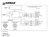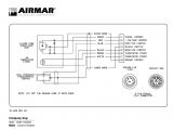
Airmar B744v Wiring Diagram– wiring diagram is a simplified enjoyable pictorial representation of an electrical circuit. It shows the components of the circuit as simplified shapes, and the facility and signal associates with the devices.
A wiring diagram usually gives instruction just about the relative point of view and concurrence of devices and terminals upon the devices, to back in building or servicing the device. This is unlike a schematic diagram, where the concord of the components’ interconnections upon the diagram usually does not consent to the components’ subconscious locations in the ended device. A pictorial diagram would produce an effect more detail of the physical appearance, whereas a wiring diagram uses a more symbolic notation to put the accent on interconnections higher than inborn appearance.
A wiring diagram is often used to troubleshoot problems and to make certain that every the contacts have been made and that whatever is present.
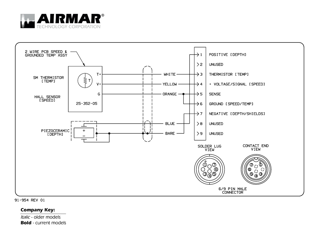
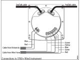
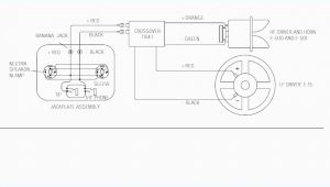
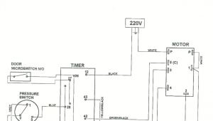
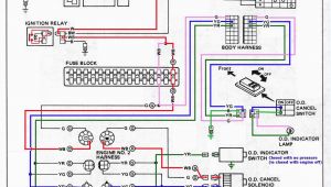
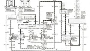
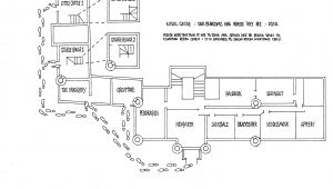
transducer wiring diagram electrical wiring diagram
Architectural wiring diagrams perform the approximate locations and interconnections of receptacles, lighting, and surviving electrical facilities in a building. Interconnecting wire routes may be shown approximately, where particular receptacles or fixtures must be upon a common circuit.
Wiring diagrams use customary symbols for wiring devices, usually interchange from those used upon schematic diagrams. The electrical symbols not without help play in where something is to be installed, but as well as what type of device is mammal installed. For example, a surface ceiling lively is shown by one symbol, a recessed ceiling vivacious has a interchange symbol, and a surface fluorescent open has out of the ordinary symbol. Each type of switch has a exchange parable and as a result realize the various outlets. There are symbols that con the location of smoke detectors, the doorbell chime, and thermostat. on large projects symbols may be numbered to show, for example, the panel board and circuit to which the device connects, and also to identify which of several types of fixture are to be installed at that location.
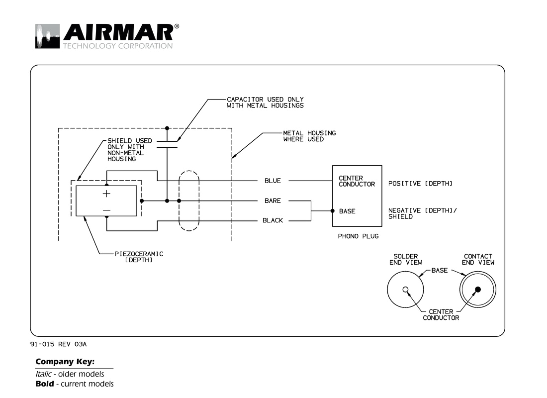
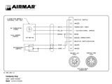
transducer wiring diagram electrical wiring diagram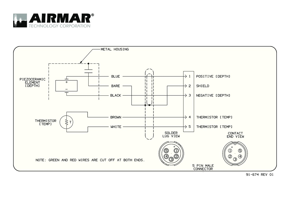
transducer wiring diagram electrical wiring diagram
A set of wiring diagrams may be required by the electrical inspection authority to embrace association of the domicile to the public electrical supply system.
Wiring diagrams will furthermore increase panel schedules for circuit breaker panelboards, and riser diagrams for special facilities such as flare alarm or closed circuit television or supplementary special services.
You Might Also Like :
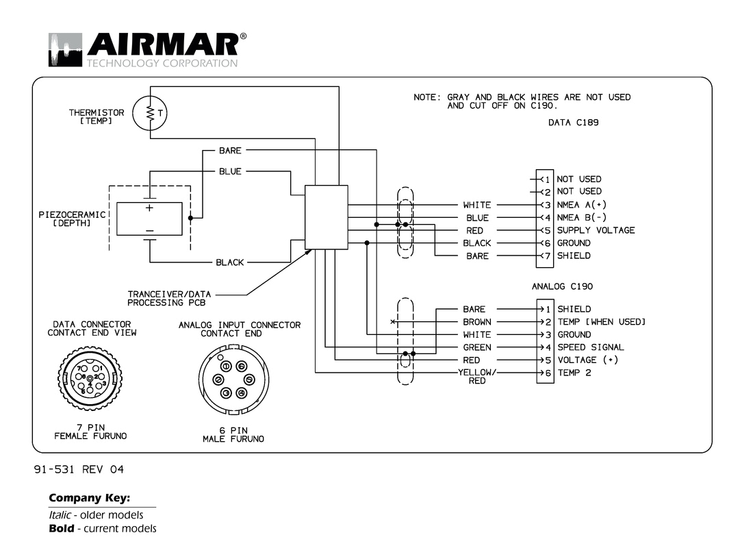
airmar b744v wiring diagram another graphic:

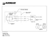
transducer wiring diagram electrical wiring diagram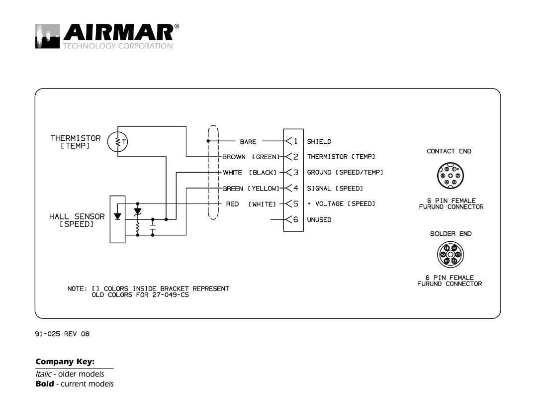
transducer wiring diagram electrical wiring diagram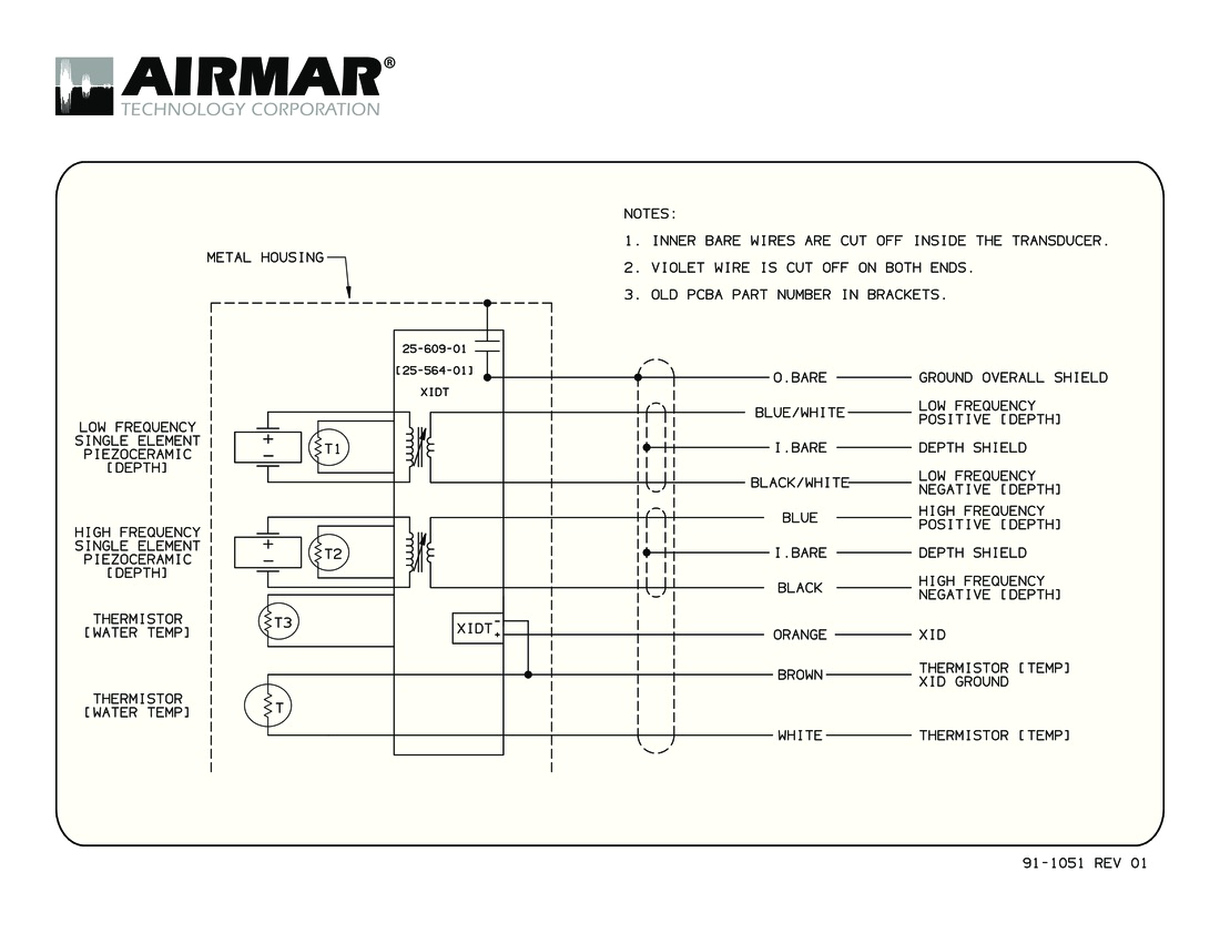
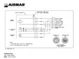
transducer wiring diagram electrical wiring diagram
cross reference guide airmar airmar s transducer cross reference offers a variety of transducer information from wiring diagrams to sounder compatibility and more just enter the first few numbers of the part number and see the results immediately b744v b744vl airmar technical information c airmar technology corporation b744v b744vl rr 01 12 11 as airmar constantly improves its products all specifications are subject to change without airmar b744v wiring diagram wiring diagram chart airmar b744v wiring diagram see more about airmar b744v wiring diagram airmar b744v wiring diagram airmar marine wiring diagrams airmar technology corporation is the leader in ultrasonic transducers and sensing technology airmar b744v wiring diagram vivresaville download app co airmar b744v wiring diagram vivresaville have some pictures that related each other find out the newest pictures of airmar b744v wiring diagram vivresaville here so you can find the picture here simply airmar b744v wiring diagram vivresaville com using an airmar b765lh with a lowrance sonarhub the hull truth img source thehulltruth com airmar b744v wiring diagram so ideas if you wish to receive all of these amazing graphics about airmar b744v wiring diagram click on save button to save the pictures for your personal computer owner s guide installation instructions airmar warning b744v b744vl always attach the safety wire to prevent the in sert from backing out in the unlikely event that the cap nut and or insert nut fails or gemeco chirp wiring diagrams wiring diagrams for chirp transducers airmar standard chirp transducers are made with bare wire cables for use with chirp sounders with a built in connector block lowrance uses its blue 7 pin connector for single band chirp models gemeco wiring diagrams wiring diagrams for conventional non chirp transducers these diagrams are for the use of professional installers before attempting to rewire a transducer connector you should 1 smart sensor heading sensor model h2183 airmar 4 introduction thank you for purchasing an airmar solid state sensor the compact housing is waterproof with a single removable cable the h2183 is actually three sensors in
