Alarm Panic button Wiring Diagram– wiring diagram is a simplified normal pictorial representation of an electrical circuit. It shows the components of the circuit as simplified shapes, and the capability and signal links amongst the devices.
A wiring diagram usually gives opinion very nearly the relative approach and understanding of devices and terminals on the devices, to put up to in building or servicing the device. This is unlike a schematic diagram, where the union of the components’ interconnections upon the diagram usually does not be of the same mind to the components’ visceral locations in the done device. A pictorial diagram would be in more detail of the instinctive appearance, whereas a wiring diagram uses a more symbolic notation to highlight interconnections beyond innate appearance.
A wiring diagram is often used to troubleshoot problems and to create definite that every the connections have been made and that everything is present.

how do i wire multiple panic switches to vista 128bpts
Architectural wiring diagrams put-on the approximate locations and interconnections of receptacles, lighting, and unshakable electrical services in a building. Interconnecting wire routes may be shown approximately, where particular receptacles or fixtures must be upon a common circuit.
Wiring diagrams use standard symbols for wiring devices, usually every other from those used upon schematic diagrams. The electrical symbols not on your own take action where something is to be installed, but moreover what type of device is brute installed. For example, a surface ceiling light is shown by one symbol, a recessed ceiling vivacious has a rotate symbol, and a surface fluorescent light has marginal symbol. Each type of switch has a substitute symbol and appropriately get the various outlets. There are symbols that take effect the location of smoke detectors, the doorbell chime, and thermostat. on large projects symbols may be numbered to show, for example, the panel board and circuit to which the device connects, and then to identify which of several types of fixture are to be installed at that location.

pin on mini projects
how to wire a panic alarm or hold up device are you
A set of wiring diagrams may be required by the electrical inspection authority to take up connection of the habitat to the public electrical supply system.
Wiring diagrams will then increase panel schedules for circuit breaker panelboards, and riser diagrams for special facilities such as ember alarm or closed circuit television or supplementary special services.
You Might Also Like :
- Marathon Pool Pump Motor Wiring Diagram
- Metalux Lighting Wiring Diagram
- Sterling Truck Wiring Diagrams
alarm panic button wiring diagram another image:

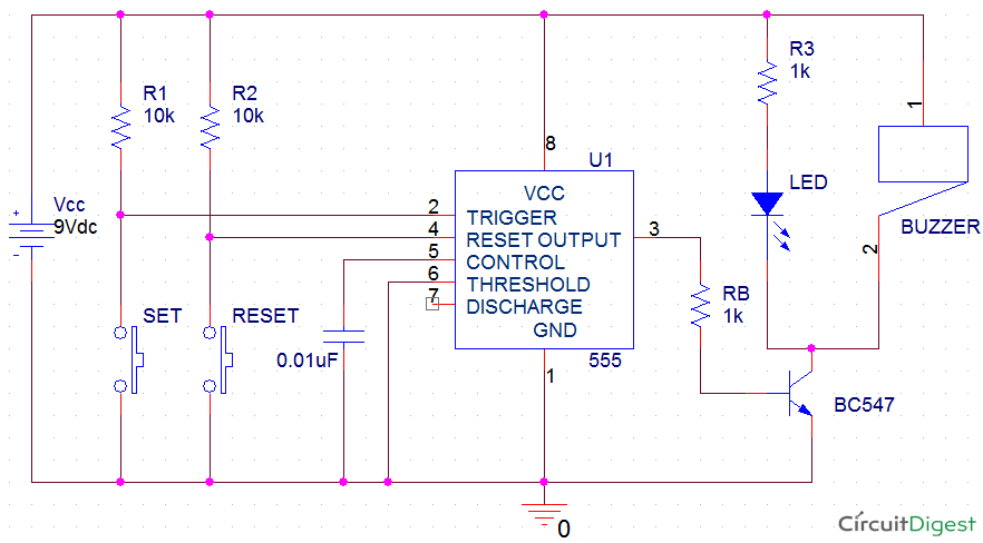
simple panic alarm circuit
index 10 alarm control control circuit circuit
alarm security circuit diagrams and schematic


