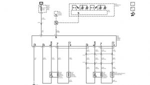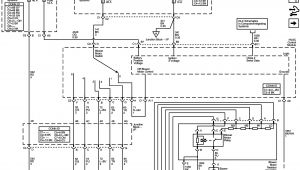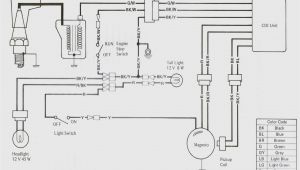
Allen Bradley 802t Limit Switch Wiring Diagram– wiring diagram is a simplified within acceptable limits pictorial representation of an electrical circuit. It shows the components of the circuit as simplified shapes, and the faculty and signal friends between the devices.
A wiring diagram usually gives instruction not quite the relative incline and bargain of devices and terminals on the devices, to help in building or servicing the device. This is unlike a schematic diagram, where the promise of the components’ interconnections upon the diagram usually does not get along with to the components’ visceral locations in the ended device. A pictorial diagram would doing more detail of the swine appearance, whereas a wiring diagram uses a more figurative notation to bring out interconnections over monster appearance.
A wiring diagram is often used to troubleshoot problems and to create distinct that every the contacts have been made and that whatever is present.
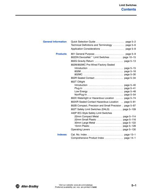
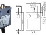
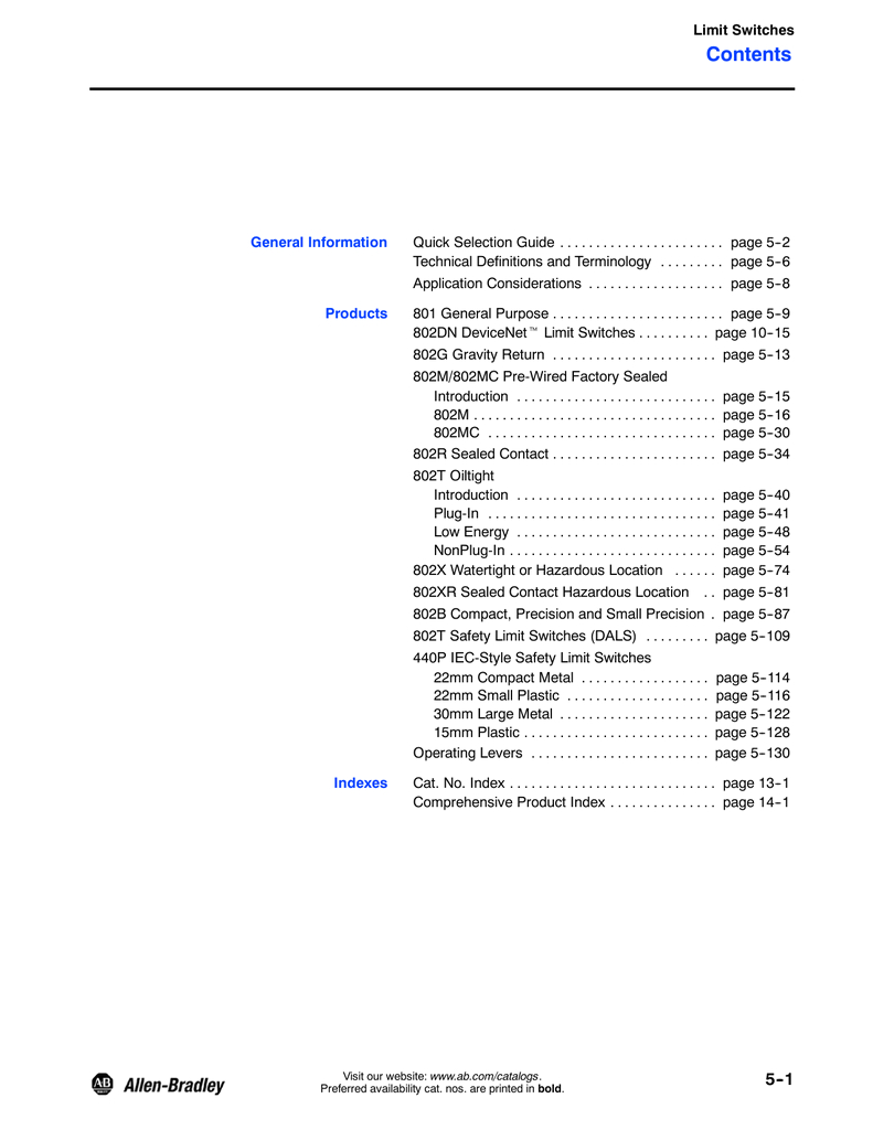
limit switches c116 sensors catatlog
Architectural wiring diagrams feat the approximate locations and interconnections of receptacles, lighting, and surviving electrical facilities in a building. Interconnecting wire routes may be shown approximately, where particular receptacles or fixtures must be on a common circuit.
Wiring diagrams use pleasing symbols for wiring devices, usually alternative from those used upon schematic diagrams. The electrical symbols not solitary affect where something is to be installed, but along with what type of device is creature installed. For example, a surface ceiling open is shown by one symbol, a recessed ceiling buoyant has a every second symbol, and a surface fluorescent roomy has unusual symbol. Each type of switch has a alternative story and for that reason accomplish the various outlets. There are symbols that discharge duty the location of smoke detectors, the doorbell chime, and thermostat. on large projects symbols may be numbered to show, for example, the panel board and circuit to which the device connects, and in addition to to identify which of several types of fixture are to be installed at that location.
limit switches technical data
allen bradley c116 ca505 en p switch corrosion
A set of wiring diagrams may be required by the electrical inspection authority to take on board attachment of the dwelling to the public electrical supply system.
Wiring diagrams will next augment panel schedules for circuit breaker panelboards, and riser diagrams for special facilities such as ember alarm or closed circuit television or other special services.
You Might Also Like :
- 2008 Chevy Impala Police Package Wiring Diagram
- Thetford C200 Wiring Diagram
- 50 Amp 4 Prong Plug Wiring Diagram
allen bradley 802t limit switch wiring diagram another photograph:

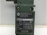
limit allen bradley 802t ap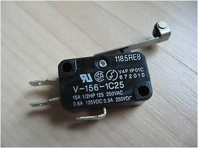
limit limit switch roller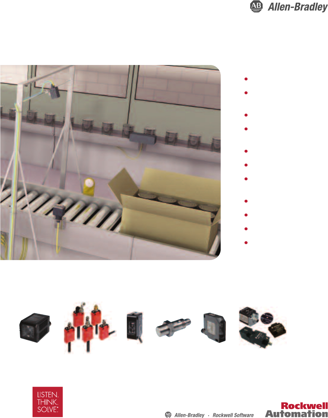
sensor guia descriptiva
802t safety limit switches platt electric supply cat no would become 802t apdy5 to order a limit switch with a factory installed 2 44 m 8 ft cable the cat no would become 802t apdy8 mini style quick disconnect to order a bulletin 802t pre wired limit switch with a 5 pin 2 circuit or 9 pin 4 circuit mini connector add the suffix j1 or j9 depending on desired wiring plug in limit switch installation and operating instructions equipment before proceeding with any repair or adjustment of the limit switch important make sure the screws used for rear mounting are not so long as to interfere with the screws used to secure the front to the base important the contacts in each switching element must have the same polarity the circuit diagram is shown on the nameplate allen bradley 802t installation instructions pdf download view and download allen bradley 802t installation instructions online four circuit direct opening action limit switch 802t switch pdf manual download allen bradley 802t installation instructions pdf download page 3 plug in limit switch installation and operating instructions notes rockwell automation publication 802t in007a mu p july 1993 page 4 allen bradley rockwell automation and rockwell software are trademarks of rockwell automation inc trademarks not belonging to rockwell automation are property of their respective companies 802t platt electric supply have ample wiring space around them the switch conduit opening is a 1 2 inch threaded pipe tap in the bottom of the housing directopeningactionposition interlockswitches bulletin 802t direct opening action limit switches have been designed for use in control reliable applications and safety applications per iso 14119 direct opening action assures that the normally closed contacts open when oiltight limit switches allen bradley oiltight limit switches bulletin 802t oiltight limit switches provide heavy duty pilot ratings small size a high degree of versatility and a rugged nema type 13 oiltight construction plug in and non plug in styles are available plug in limit switches have a head and switch body that can be replaced while leaving the wiring chamber base in place this reduces your down time by eliminating the need for rewiring upon switch replacement allen bradley 802t amp mcnaughton mckay 802t amp brand allen bradley allen bradley 802t amp limit switch nema type 4 and 13 oiltight construction plug in lever type maintained contact 2 circuit cw and ccw operation whole switch literature rockwellautomation com literature rockwellautomation com

