Apm Wiring Diagram– wiring diagram is a simplified okay pictorial representation of an electrical circuit. It shows the components of the circuit as simplified shapes, and the capacity and signal associates amongst the devices.
A wiring diagram usually gives opinion about the relative aim and conformity of devices and terminals on the devices, to incite in building or servicing the device. This is unlike a schematic diagram, where the concurrence of the components’ interconnections on the diagram usually does not come to an understanding to the components’ creature locations in the over and done with device. A pictorial diagram would work more detail of the subconscious appearance, whereas a wiring diagram uses a more symbolic notation to put the accent on interconnections higher than creature appearance.
A wiring diagram is often used to troubleshoot problems and to create sure that all the contacts have been made and that all is present.
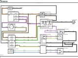
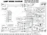
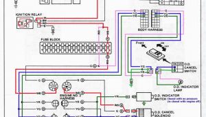
aprilaire 760 wiring diagram wire diagram database
Architectural wiring diagrams take steps the approximate locations and interconnections of receptacles, lighting, and surviving electrical facilities in a building. Interconnecting wire routes may be shown approximately, where particular receptacles or fixtures must be on a common circuit.
Wiring diagrams use adequate symbols for wiring devices, usually every other from those used on schematic diagrams. The electrical symbols not lonely behave where something is to be installed, but afterward what type of device is mammal installed. For example, a surface ceiling spacious is shown by one symbol, a recessed ceiling lighthearted has a swing symbol, and a surface fluorescent open has complementary symbol. Each type of switch has a every second symbol and in view of that pull off the various outlets. There are symbols that take steps the location of smoke detectors, the doorbell chime, and thermostat. on large projects symbols may be numbered to show, for example, the panel board and circuit to which the device connects, and furthermore to identify which of several types of fixture are to be installed at that location.
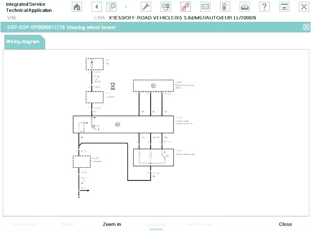
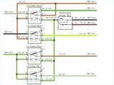
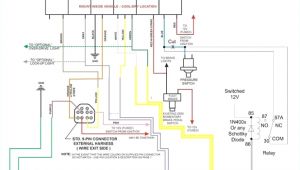
2001 grand prix stereo wiring diagram marquis fuel pump jeep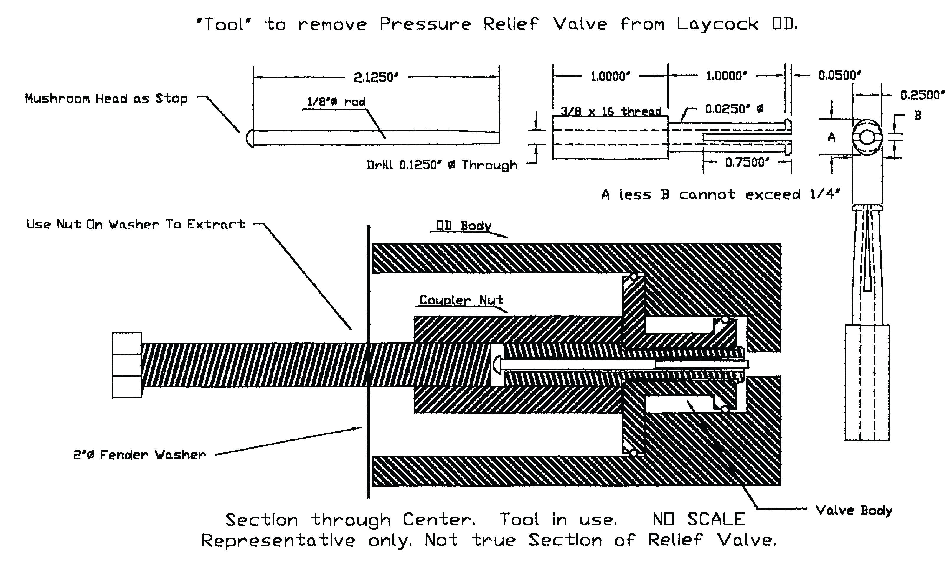
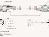
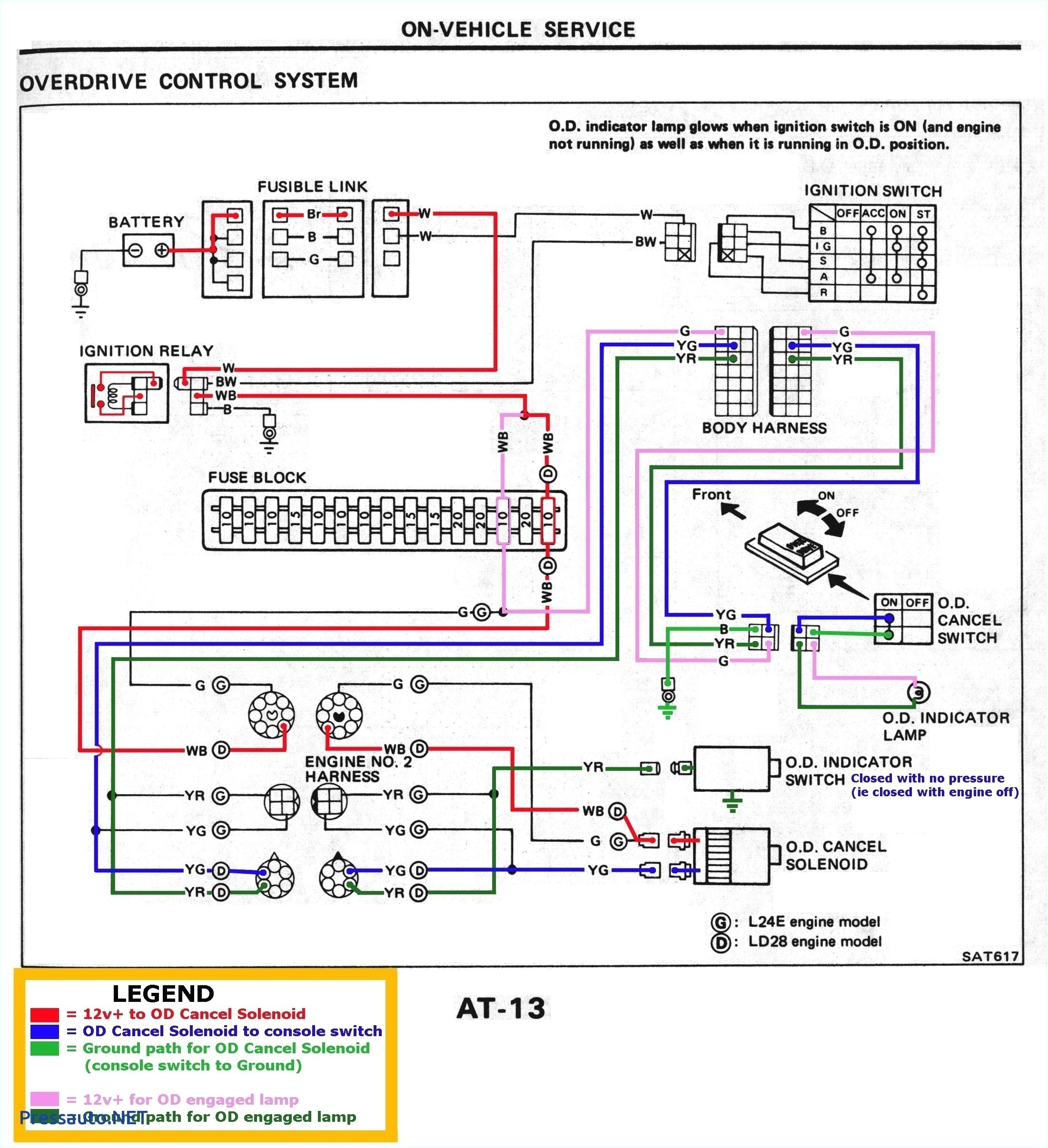
guitar amp wiring diagram awesome hohner encoder wiring diagram
A set of wiring diagrams may be required by the electrical inspection authority to espouse membership of the habitat to the public electrical supply system.
Wiring diagrams will along with tally panel schedules for circuit breaker panelboards, and riser diagrams for special services such as fire alarm or closed circuit television or other special services.
You Might Also Like :
- Boiler Emergency Shut Off Switch Wiring Diagram
- Sx460 Avr Wiring Diagram Pdf
- Leviton Double Switch Wiring Diagram
apm wiring diagram another graphic:
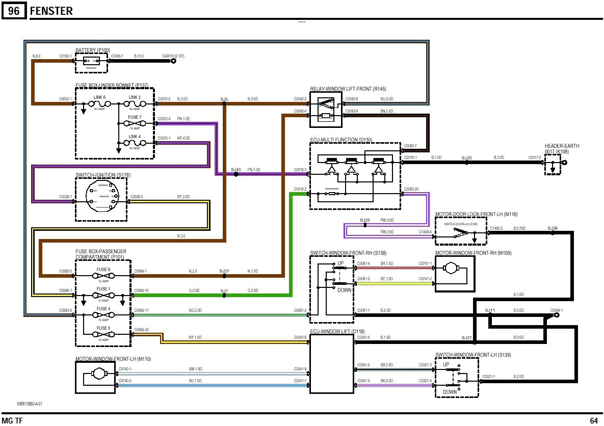
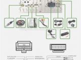
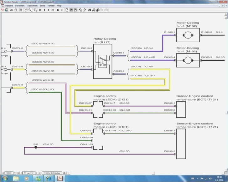
alpine ktp 445u wiring diagram free wiring diagram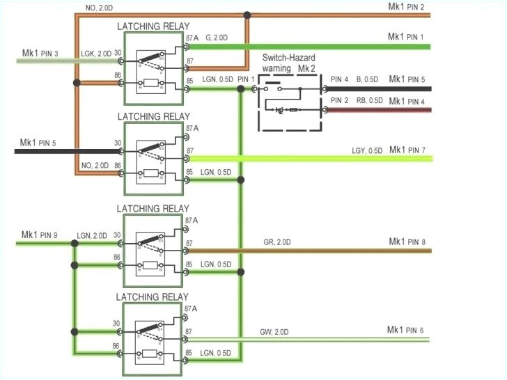
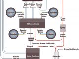
4 channel amp wiring diagram new 25 fresh 2 amps 1 sub wiring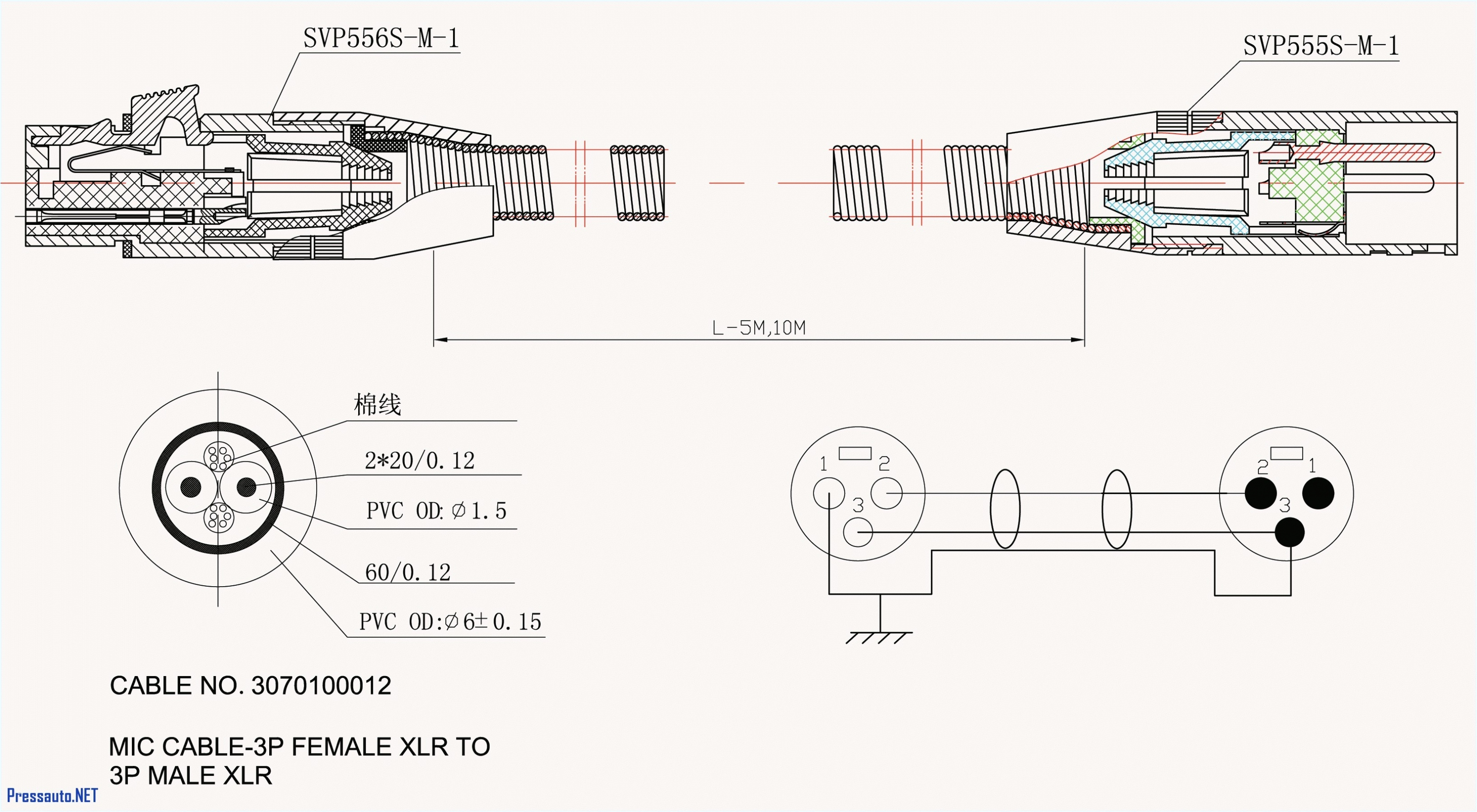
wiring diagram for sub and amp awesome 6 subwoofer wiring diagram
archived apm2 x wiring quickstart copter documentation apm wiring diagram the diagram below is an overview of how an apm2 can be connected to a receiver esc gps and even a camera gimbal archived apm2 x wiring quickstart plane documentation archived apm2 x wiring quickstart example wiring diagram for a bixler plane with apm example wiring diagram for abixler plane with apm inputs connect your rc receiver to apm2 s inputs with female to female cables in the order shown above each channel that you want apm to control should be connected to an input on the apm board typically the mode switch apm input 8 for plane is fpv part 12 installing wiring apm 2 6 telemetry radio and minumosd reviewing wiring schematic and hook up wires for the ardupilot mega 2 6 to the ezuhf receiver we make extension cables for the 3dr telemetry radio and minumosd apm wiring diagram wiring diagram and schematics apm wiring diagram you are welcome to our site this is images about apm wiring diagram posted by alice ferreira in apm category on jul 03 2019 arducopter 2 8 wiring you still need an esc example wiring diagram for a bixler plane with apm connections between rc receiver and ardupilot mega v2 board this can be dune by cutting the red wire on all but one of the esc s or by using a special jan 20 tim dickinson the op has the apm which is a clone and it s different from apm pin layout ardupilot 2 5 schematic pdf 19 the diagrams on the page below is for v1 and v2 which have molex clickmate apm 2 6 receiver wiring apm 2 6 schematic pdf apm 2 8 manual pdf arducopter 2 8 apm 2 6 wiring wiring diagrams 19 apm 2 6 vs 2 8 wiring diagram ardupilot mega 2 find deals on ardupilot in electronics on amazon ardupilot 2 5 schematic pdf download http it is the world most popular photo editing and ing diagrams are giv en sho wing comparisons of the colour and magnitude from the landolt publication with those of the ukir tv alues references mmcasali tgha w arden jcmt ukir t newsletter and h ttp wwwjac hha w aiiedu ukir t astronom y ca lib cmc carlsb erg meridian catalogue la p alma cop enhagen univ ersit y observ atory ro al green wic h observ atory and real instituto y observ atorio de la ardupilot apm 2 6 wiring minumosd apm telemetry radio power module xuav mini talon fpv part 4 reviewing wiring schematic and hook up wires for the ardupilot mega 2 6 to the ezuhf receiver we connect the cables for the 3dr telemetry radio and minumosd all to be mounted on the mini talon apm2 8 wiring diagram multirotors ardupilot discourse could someone please direct me to a wiring diagram specific to each pin out not block diagram to the following gps telemetry i2c and pin out for each sensor connector across the left side as to what they do apm helicopter 2 6 wiring help please ardupilot discourse i basically have the same setup futaba system apm 2 8 and a trex 450 and connected the receiver to the apm as described above on the first wiring picture and use arducopter 3 2 1 and mission planner
