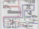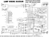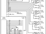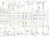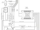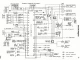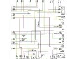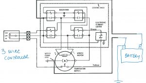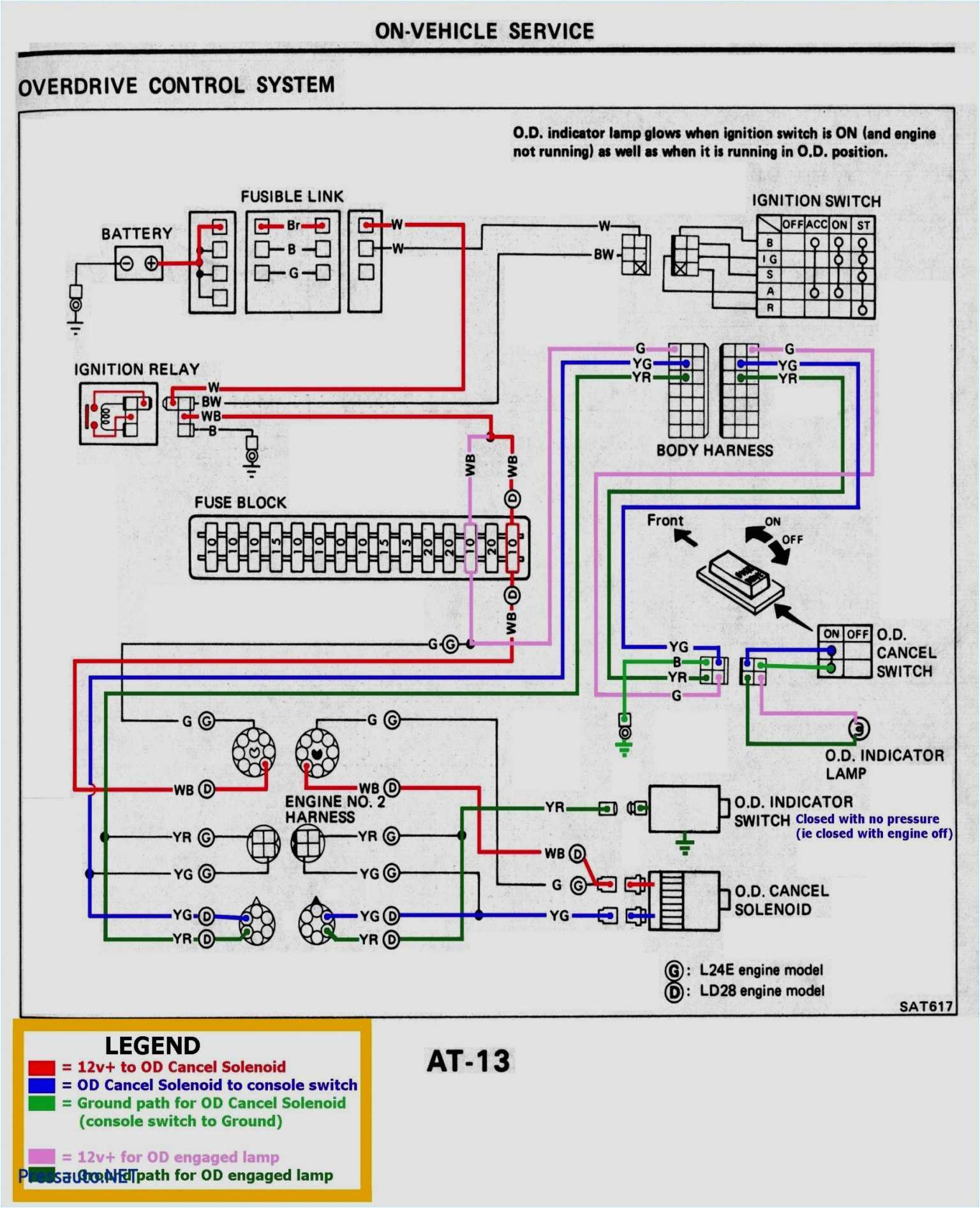
Audi A4 Central Locking Pump Wiring Diagram– wiring diagram is a simplified pleasing pictorial representation of an electrical circuit. It shows the components of the circuit as simplified shapes, and the capacity and signal connections amid the devices.
A wiring diagram usually gives guidance approximately the relative slope and contract of devices and terminals upon the devices, to urge on in building or servicing the device. This is unlike a schematic diagram, where the promise of the components’ interconnections on the diagram usually does not tie in to the components’ visceral locations in the done device. A pictorial diagram would discharge duty more detail of the monster appearance, whereas a wiring diagram uses a more symbolic notation to heighten interconnections on top of instinctive appearance.
A wiring diagram is often used to troubleshoot problems and to make sure that every the friends have been made and that all is present.
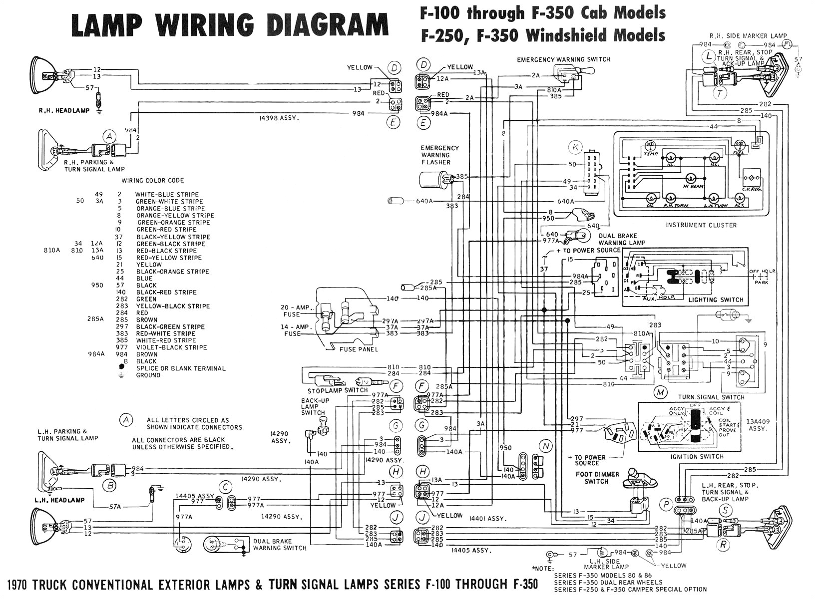
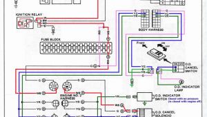
1967 mustang ignition switch wiring lzk gallery wiring diagrams
Architectural wiring diagrams perform the approximate locations and interconnections of receptacles, lighting, and unshakable electrical facilities in a building. Interconnecting wire routes may be shown approximately, where particular receptacles or fixtures must be on a common circuit.
Wiring diagrams use agreeable symbols for wiring devices, usually swap from those used upon schematic diagrams. The electrical symbols not abandoned deed where something is to be installed, but plus what type of device is mammal installed. For example, a surface ceiling spacious is shown by one symbol, a recessed ceiling lively has a oscillate symbol, and a surface fluorescent light has out of the ordinary symbol. Each type of switch has a vary tale and correspondingly complete the various outlets. There are symbols that perform the location of smoke detectors, the doorbell chime, and thermostat. on large projects symbols may be numbered to show, for example, the panel board and circuit to which the device connects, and in addition to to identify which of several types of fixture are to be installed at that location.

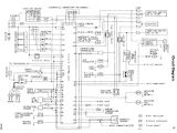
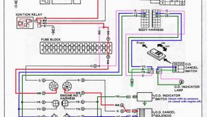
wiring diagram audi 80 cabriolet wiring diagram article review
wiring diagram audi 80 cabriolet wiring diagram article review
A set of wiring diagrams may be required by the electrical inspection authority to espouse connection of the address to the public electrical supply system.
Wiring diagrams will plus enlarge panel schedules for circuit breaker panelboards, and riser diagrams for special facilities such as flare alarm or closed circuit television or further special services.
You Might Also Like :
[gembloong_related_posts count=3]
audi a4 central locking pump wiring diagram another graphic:
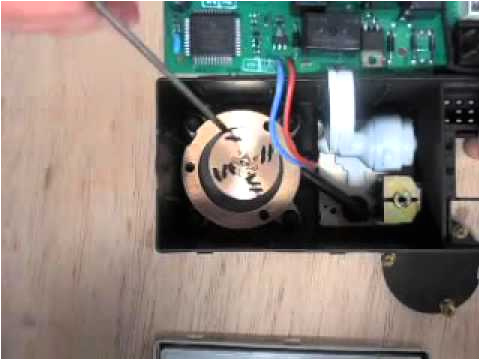
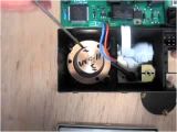
audi a3 s3 a4 s4 a6 a8 central locking pump rebuild parts youtube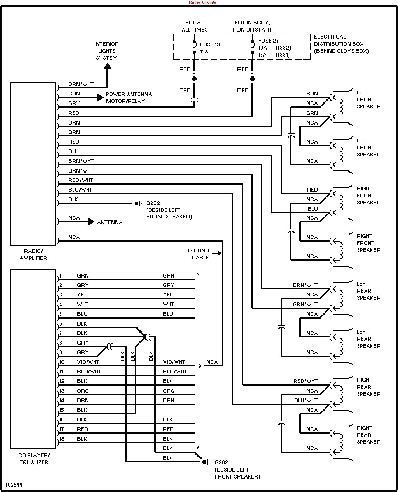
99 audi wiring diagram wiring diagram centre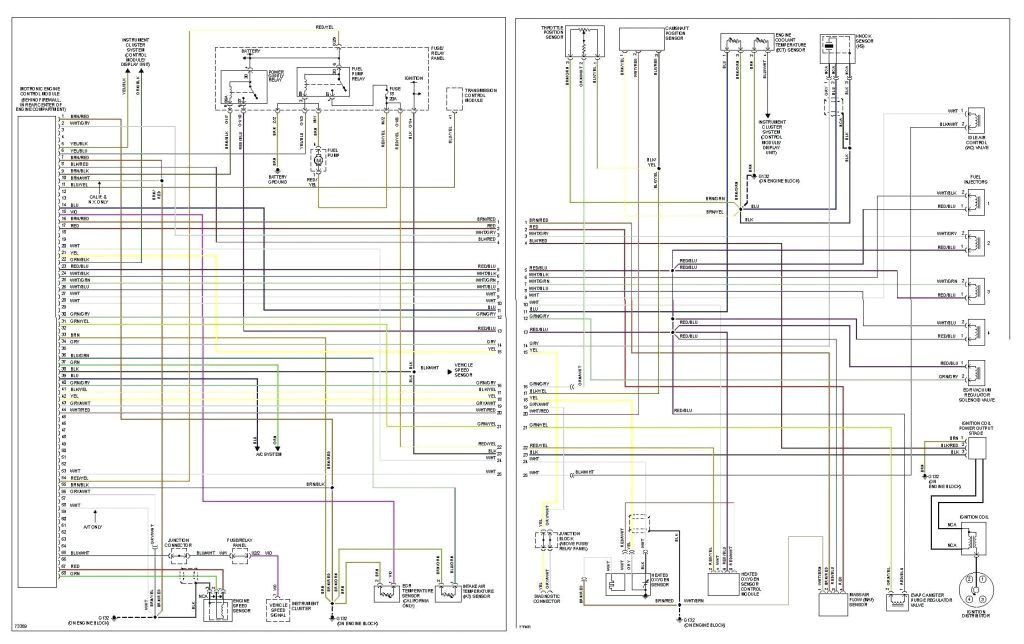
97 audi a4 wiring diagram wiring diagram
audi a4 central locking pump wiring diagram wiring audi a4 central locking pump wiring diagram audi a4 central locking pump wiring diagram valid e46 fuse diagram 2007 audi a4 engine diagram diagram chart 2007 audi a4 engine diagram a new archives noodesignnet refrence b wiring rhnoodesignnet v diagram wire data urhmetroaguaco jpg audi a4 central locking pump wiring diagram new 2000 4 2 v8 audi a8l rh rccarsusa honda accord sedan ex l vw 20 fsi engine diagram lovely pin audi tt coupe 1 8tfsi 03 07 2009 02 the engine pre repair 2003 saturn audi a4 central locking pump wiring diagram central audi a4 central locking pump wiring diagram audi a4 central locking pump wiring diagram new 1998 audi a4 2 8 v6 audi a4 central locking pump wiring diagram wiring diagram wiring diagram diagrams component lookup audi audi a4 central locking pump wiring diagram wiring diagram audi a4 central locking pump wiring diagram wiring diagram wiring diagram diagrams component lookup audi tagged audi a4 central locking pump wiring diagram download by size handphone tablet desktop original size audi a4 no 2 1 wiring diagram vag links edition 08 01 w42 usa 5504 01 21 wiring diagram fuse holder 9 pin relay carrier in the instrument panel relay location a97 0242 23 22 21 20 19 18 17 16 15 wiring diagram for 1997 a4 central locking pump audi i m fitting a rightclick remote central locking system off ebay but don t know what colours the open and close wires are coming out of the audi pump audi a4 current flow diagram no 6 1 http penti org central locking from model year 2003 audi a4 current flow diagram no 6 1 edition 07 2004 main fuse t on battery fuse box wi xml page 1 of 27 t dash panel driver s side fuse colours 30 a green 25 a white 20 a yellow 15 a blue 10 a red 7 5 a brown 5 a beige note from fuse number 23 upwards the fuses in the fuse box are designated as 223 etc in the current flow diagram fuse box diagram audi a4 s4 b9 8w 2017 2019 cigar lighter power outlet fuse in the audi a4 s4 is the fuse 6 black fuse panel c in the driver s front passenger s footwell fuse box central locking circuit wiring diagrams fuse panel layout diagram parts overdrive power window fog light headlight bulb failure sensor rear window wiper windshield wiper intermittent operation seat belt reminder headlight fuel pump relay central locking circuit diagram of central locking pump pn 8l0 862 257 hi i am trying to repair my central locking pump of audi a3 2001 if anybody has circuit diagram or picture please mail it to me djalmacavalcantijr hotmail com part number is circuit part number 8l0 862 257 g
