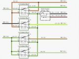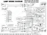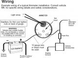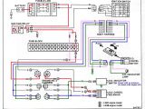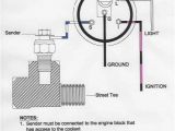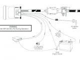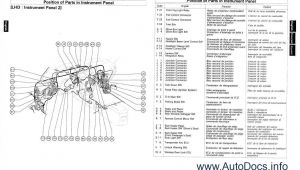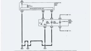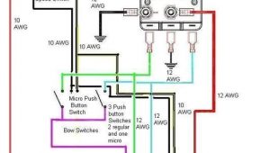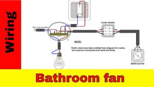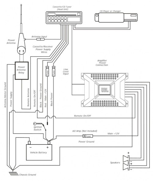
Autometer Amp Gauge Wiring Diagram– wiring diagram is a simplified suitable pictorial representation of an electrical circuit. It shows the components of the circuit as simplified shapes, and the knack and signal associates amid the devices.
A wiring diagram usually gives guidance practically the relative position and harmony of devices and terminals on the devices, to back up in building or servicing the device. This is unlike a schematic diagram, where the concurrence of the components’ interconnections upon the diagram usually does not say yes to the components’ subconscious locations in the finished device. A pictorial diagram would play a role more detail of the bodily appearance, whereas a wiring diagram uses a more symbolic notation to highlight interconnections more than subconscious appearance.
A wiring diagram is often used to troubleshoot problems and to make definite that all the friends have been made and that everything is present.
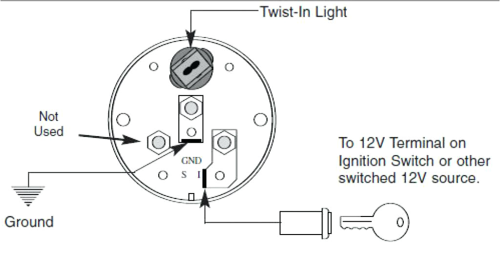
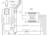
pro comp wiring diagram wiring diagram technic
Architectural wiring diagrams play a part the approximate locations and interconnections of receptacles, lighting, and unshakable electrical services in a building. Interconnecting wire routes may be shown approximately, where particular receptacles or fixtures must be on a common circuit.
Wiring diagrams use welcome symbols for wiring devices, usually substitute from those used on schematic diagrams. The electrical symbols not solitary appear in where something is to be installed, but plus what type of device is physical installed. For example, a surface ceiling lighthearted is shown by one symbol, a recessed ceiling roomy has a alternative symbol, and a surface fluorescent vivacious has marginal symbol. Each type of switch has a stand-in parable and suitably accomplish the various outlets. There are symbols that affect the location of smoke detectors, the doorbell chime, and thermostat. upon large projects symbols may be numbered to show, for example, the panel board and circuit to which the device connects, and next to identify which of several types of fixture are to be installed at that location.
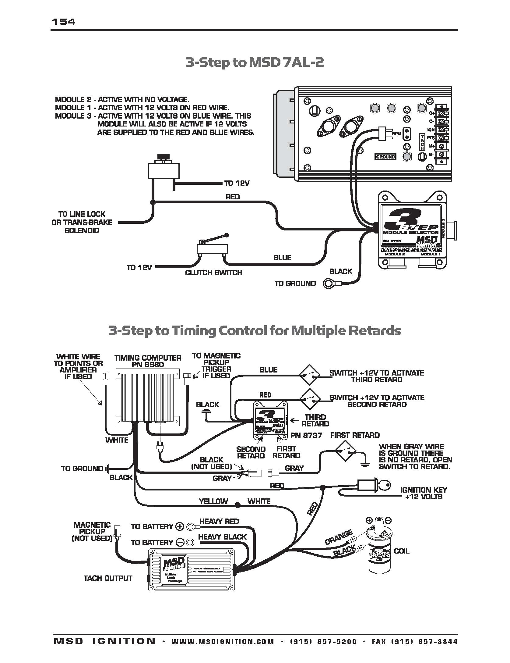
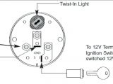
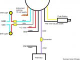
autometer tach wiring wiring diagram technic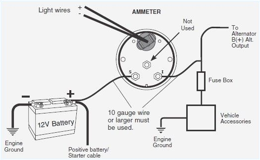
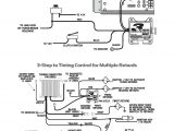
autometer tach wiring wiring diagram technic
A set of wiring diagrams may be required by the electrical inspection authority to take on board membership of the residence to the public electrical supply system.
Wiring diagrams will afterward tally up panel schedules for circuit breaker panelboards, and riser diagrams for special facilities such as flame alarm or closed circuit television or supplementary special services.
You Might Also Like :
[gembloong_related_posts count=3]
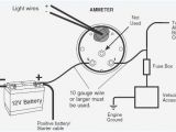
autometer amp gauge wiring diagram another graphic:
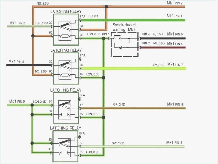
sunpro voltmeter wiring diagram wiring diagram technic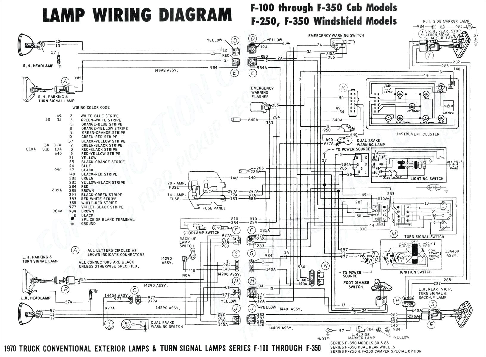
wiring diagram gl1100 auto meter wiring diagram name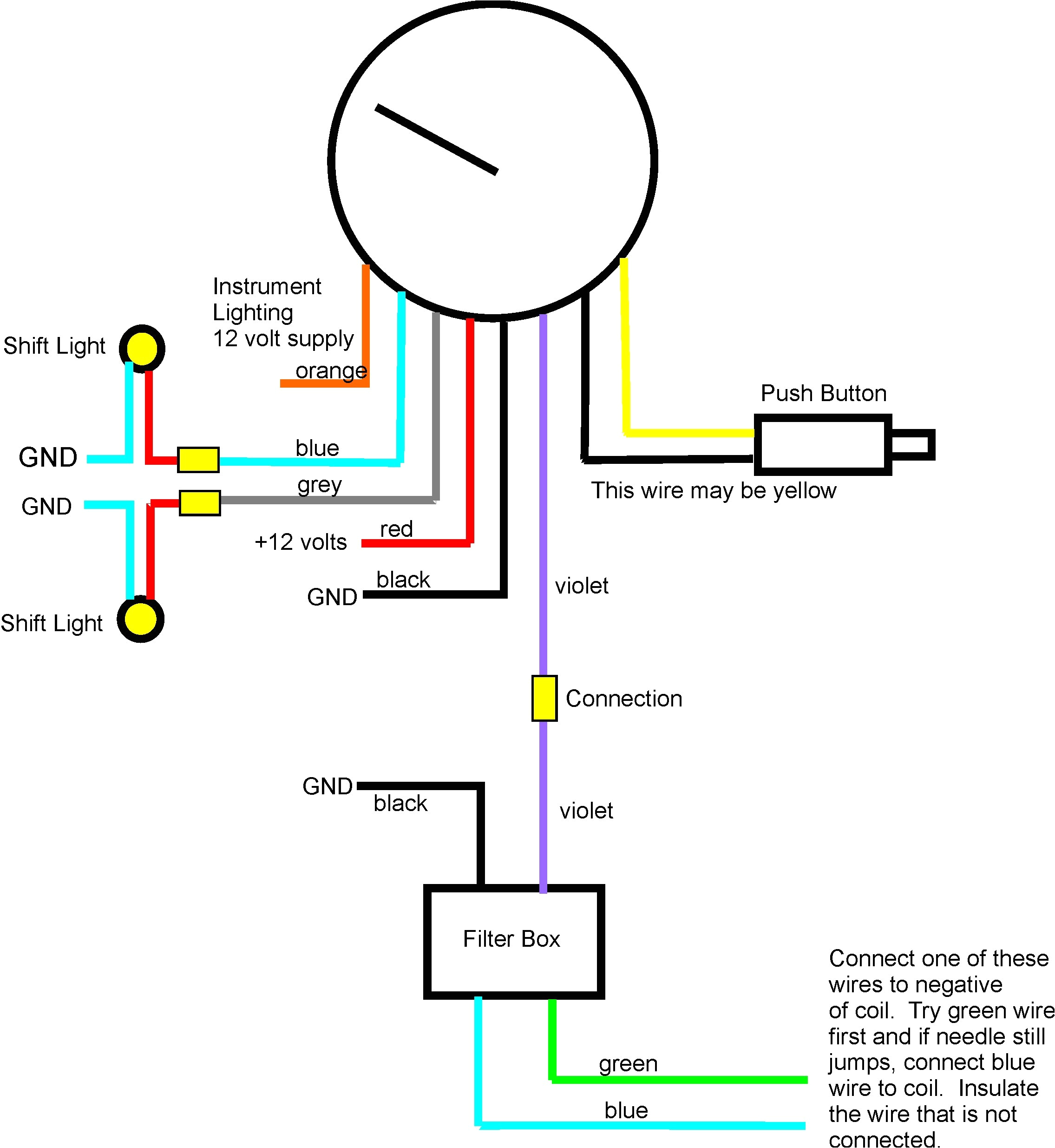
wiring diagram gl1100 auto meter wiring diagram name
how to wire an auto meter amp gauge it still runs use the wiring diagram and test light or multi meter to locate the positive wire from the alternator to the fuse block then locate any wire that has power with the ignition off auto meter tach gauge wiring diagram articlevault info auto meter electronic tachometer autometer amp gauge wiring diagram arbortech us autometer tach wiring msd autometer amp gauge wiring diagram autometer oil pressure gauge wiring diagram and temp free template auto meter tach gauge wiring diagram wiring diagram auto gauge tachometer new luxury autometer tach wiring diagram diagram resources installation support auto meter resources installation support resources installation support autometer s gauges are only as good as the installation make sure your gauge is installed right and works correctly with our installation support instructional downloads find product manuals and wiring diagrams for your auto meter product find instructions vehicle search find vehicle specific installation information autometer tach wiring diagram free wiring diagram variety of autometer tach wiring diagram a wiring diagram is a streamlined standard pictorial representation of an electrical circuit it reveals the components of the circuit as simplified shapes and also the power and also signal connections in between the devices auto meter wiring diagram free wiring diagram collection of auto meter wiring diagram a wiring diagram is a streamlined traditional pictorial representation of an electric circuit it shows the components of the circuit as streamlined shapes and also the power as well as signal connections between the devices auto meter wiring diagram wiring diagram chart auto meter wiring diagram autometer boost gauge wiring diagram auto meter volt for temp to pro autometer amp gauge wiring diagram wiring diagram chart autometer amp gauge wiring diagram see more about autometer amp gauge wiring diagram autometer amp gauge wiring diagram amp gauge wiring classic instruments amp gauge wiring 1 always disconnect the ground lead from the vehicle battery before wiring any gauge 2 classic instruments amp gauge should only be used on vehicles with alternators rated at 60 amps or autometer pro comp tach wiring diagram wordpress com pro comp auto meter gauges wiring diagram boat volt gauge wiring diagram fuel manufacture gauges auto gauge tach wiring diagram thank you systems how they work how they work with your auto meter tach how to install a car volt amp gauge with pictures wikihow volt and amp gauges monitor your vehicle s electrical system the ammeter measures the amount of current to the battery whereas the volt gauge measures continuous battery voltage
