Bodine Eli S 100 Wiring Diagram– wiring diagram is a simplified good enough pictorial representation of an electrical circuit. It shows the components of the circuit as simplified shapes, and the knack and signal associates amongst the devices.
A wiring diagram usually gives information approximately the relative perspective and contract of devices and terminals on the devices, to support in building or servicing the device. This is unlike a schematic diagram, where the harmony of the components’ interconnections on the diagram usually does not go along with to the components’ monster locations in the done device. A pictorial diagram would action more detail of the creature appearance, whereas a wiring diagram uses a more figurative notation to highlight interconnections beyond instinctive appearance.
A wiring diagram is often used to troubleshoot problems and to create definite that all the connections have been made and that everything is present.

imp2 increases mouse skeletal muscle mass and voluntary
Architectural wiring diagrams act out the approximate locations and interconnections of receptacles, lighting, and permanent electrical services in a building. Interconnecting wire routes may be shown approximately, where particular receptacles or fixtures must be upon a common circuit.
Wiring diagrams use gratifying symbols for wiring devices, usually alternating from those used on schematic diagrams. The electrical symbols not unaided behave where something is to be installed, but also what type of device is physical installed. For example, a surface ceiling buoyant is shown by one symbol, a recessed ceiling fresh has a every other symbol, and a surface fluorescent lighthearted has unusual symbol. Each type of switch has a alternative tale and fittingly get the various outlets. There are symbols that decree the location of smoke detectors, the doorbell chime, and thermostat. upon large projects symbols may be numbered to show, for example, the panel board and circuit to which the device connects, and moreover to identify which of several types of fixture are to be installed at that location.

pdf oleoyl serine an endogenous n acyl amide modulates
operating and service manu al pdf document
A set of wiring diagrams may be required by the electrical inspection authority to assume attachment of the habitat to the public electrical supply system.
Wiring diagrams will also tally up panel schedules for circuit breaker panelboards, and riser diagrams for special facilities such as blaze alarm or closed circuit television or supplementary special services.
You Might Also Like :
- 1996 Cadillac Deville Radio Wiring Diagram
- Detroit Ddec 4 Ecm Wiring Diagram
- Off Road Light Wiring Diagram with Relay
bodine eli s 100 wiring diagram another picture:

quantitative time resolved phosphoproteomic analysis of mast
down regulation of pkm2 decreases fasn expression in bladder
pdf the peroxisome proliferator activated receptor ppar
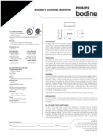
wiring diagram for philips bodine eli s 100 18 10 2018 18 10 2018 1 comments on wiring diagram for philips bodine eli s 100 eli s inverter for led emergency lighting philips bodine for led emergency lighting the eli s provides a dimming control output bodine eli sv led emergency driver w vac led emergency driver vac 60hz maximum load power including ac ballast driver watts catalog page bodine installation manual bodine philips eli s 100 installation instructions use only philips bodine part number prt00133 as replacement batteries wiring diagram maintenance operation during normal operation ac power is supplied to the ac ballast driver through the eli s 100 and the batteries charge connecting the inverter connector wires red and white enables the emergency circuit and supplies power to the control monitor circuit when ac power fails the philips bodine eli series installation and operating page 5 wiring diagram step 7 join the inverter connector apply power after installation is complete apply ac power and join the inverter connector inside the case then screw the front cover to the case at this point power should be connected to both the ac ballast and the eli s 100 and the charging indicator light on the test switch should illuminate indicating the battery is charging eli s 100 signify eli s 100 100va pure sine wave output nano inverter automatic output voltage select patented automatic dimming 0 10v of connected loads download spec sheet downloads instruction sheet product summary ul listed for the us and canada ul924 emergency lighting compliant factory or field installation indoor and damp illumination time 90 minutes maximum connected load power eli s 10 signify wiring diagram section of instructions note the backup nano inverter may be installed in close proximity to the fixture or remote from the fixture the maximum remote distance using 16 awg wire is 100 ft contact the factory for more information the ac ballast driver receives power from the backup nano inverter identify the output wires of the backup nano inverter by the presence of bodine b100 emergency ballast wiring diagram free wiring collection of bodine b100 emergency ballast wiring diagram a wiring diagram is a streamlined traditional photographic representation of an electrical circuit it shows the elements of the circuit as streamlined shapes as well as the power and also signal links between the tools eli s 100 emergency lighting inverter philips bodine the philips bodine eli s 100 emergency lighting inverter works in conjunction with a fluorescent or led fixture to create an emergency lighting system the eli s 100 operates a maximum load of 100 w at unity power factor it allows the connected fixture s to be on off switched or dimmed without affecting emergency operation each unit consists of two sealed lead acid batteries charger and bodine b100 emergency battery installation instructions select the appropriate wiring diagram on back to connect the emergency ballast to the ac ballast and lamp s make sure all connections are in accordance with the national electrical code and any local regulations after installation is complete supply ac power to the emergency ballast and join the inverter connector at this point power should be connected to both the ac ballast and supplementary materials for 100 02 20 40 60 80 p s p s ry figures 4 3 i c 3 o c wavele 00 60 tim 46 hema hydroge ilicon hydrogel hema hydroge ilicon hydrogel h 3 4 si o ngth nm 080 phema h silicone h e min 81012 l treated treated l 5 5 c o 0 1000 ydrogel ydrogel 14 16 transmittance 88 90 92 94 96 98 100 102 b c equilibrium water content 0 10 20 30 40 n 5 9 13 d f w 1000 silico lotra 2 43 5 u v u e wiring leds correctly series parallel circuits explained wiring leds correctly series parallel circuits explained february 11 2019 by brooke sault 151 666 views hopefully those looking for practical information on electrical circuits and wiring led components found this guide first it s likely though you ve already read the wikipedia page about series and parallel circuits here maybe a few other google search results on the subject


