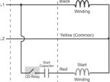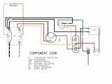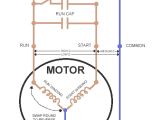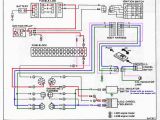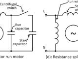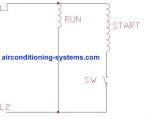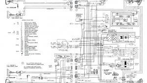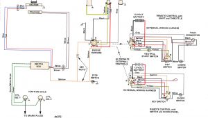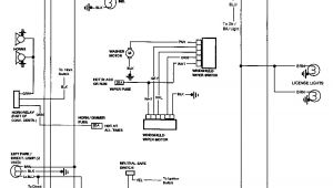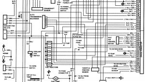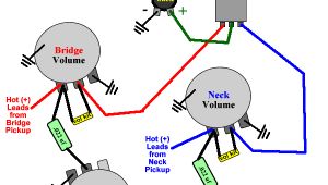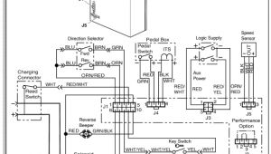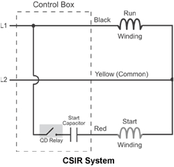
Capacitor Start Capacitor Run Motor Wiring Diagram– wiring diagram is a simplified usual pictorial representation of an electrical circuit. It shows the components of the circuit as simplified shapes, and the skill and signal associates with the devices.
A wiring diagram usually gives guidance more or less the relative slant and settlement of devices and terminals upon the devices, to put up to in building or servicing the device. This is unlike a schematic diagram, where the covenant of the components’ interconnections on the diagram usually does not allow to the components’ bodily locations in the ended device. A pictorial diagram would deed more detail of the beast appearance, whereas a wiring diagram uses a more figurative notation to draw attention to interconnections exceeding inborn appearance.
A wiring diagram is often used to troubleshoot problems and to make sure that all the links have been made and that anything is present.
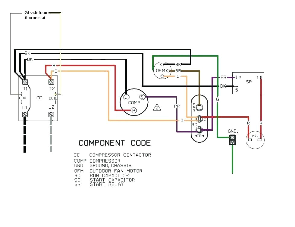
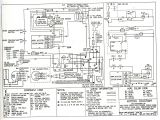
heil air handler wiring diagram wiring diagram name
Architectural wiring diagrams show the approximate locations and interconnections of receptacles, lighting, and unshakable electrical services in a building. Interconnecting wire routes may be shown approximately, where particular receptacles or fixtures must be on a common circuit.
Wiring diagrams use standard symbols for wiring devices, usually swap from those used on schematic diagrams. The electrical symbols not and no-one else con where something is to be installed, but as a consequence what type of device is brute installed. For example, a surface ceiling light is shown by one symbol, a recessed ceiling open has a alternating symbol, and a surface fluorescent blithe has out of the ordinary symbol. Each type of switch has a alternative fable and suitably accomplish the various outlets. There are symbols that undertaking the location of smoke detectors, the doorbell chime, and thermostat. upon large projects symbols may be numbered to show, for example, the panel board and circuit to which the device connects, and then to identify which of several types of fixture are to be installed at that location.
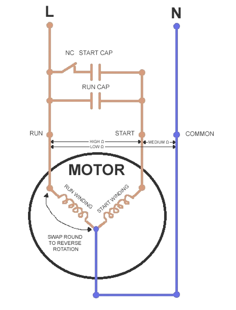
4 capacitor wiring diagram wiring diagrams second
start run capacitor wiring diagram samsung rs2555bb wiring diagram
A set of wiring diagrams may be required by the electrical inspection authority to espouse relationship of the quarters to the public electrical supply system.
Wiring diagrams will moreover adjoin panel schedules for circuit breaker panelboards, and riser diagrams for special facilities such as flare alarm or closed circuit television or supplementary special services.
You Might Also Like :
- Dragonhawk Tattoo Power Supply Wiring Diagram
- Johnson Outboard Wiring Diagram Pdf
- Ego C Twist Wiring Diagram
capacitor start capacitor run motor wiring diagram another picture:
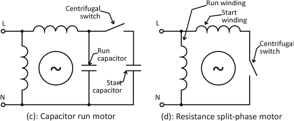
what is the wiring of a single phase motor quora
hvac training dual run capacitor wiring youtube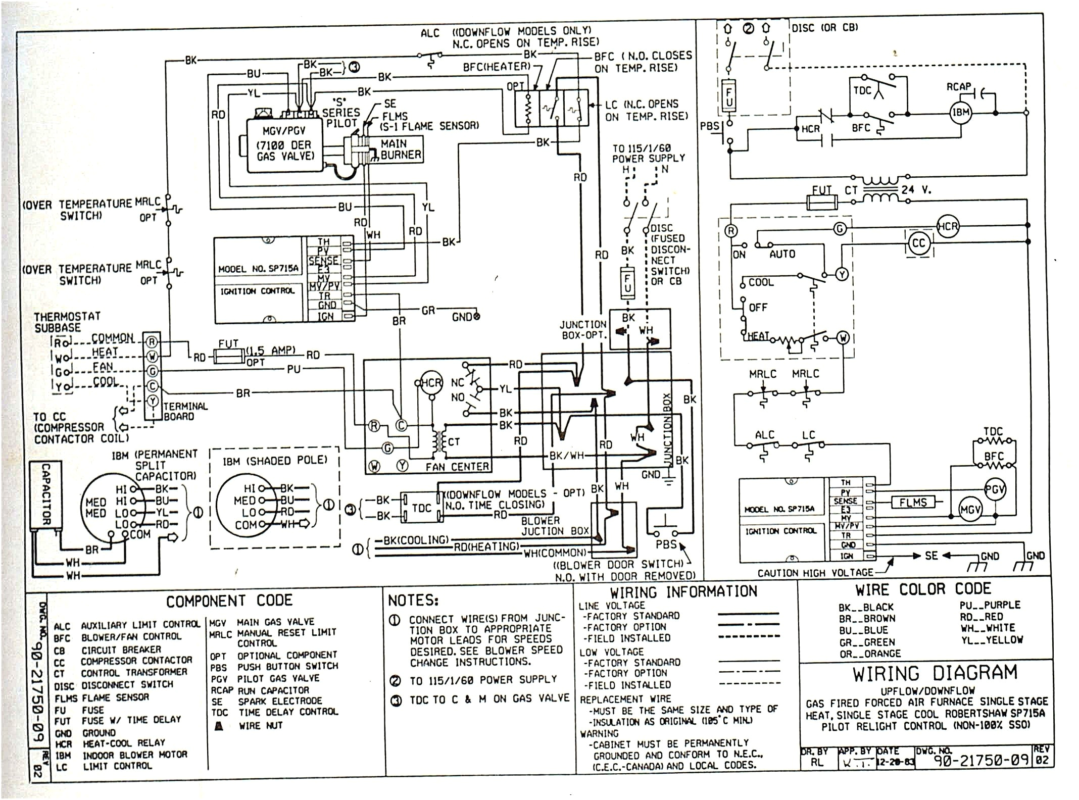
heil air handler wiring diagram wiring diagram name
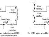
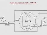
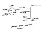
capacitor start capacitor run motor circuit globe the figure below shows the phasor diagram of the capacitor start capacitor run motor fig a shows the phasor diagram when at the starting both the capacitor are in the circuit and ϕ 90 fig b shows the phasor when the starting capacitor is disconnected and ϕ becomes equal to 90 wiring diagram capacitor start run motor diagram single phase motor wiring diagram with capacitor start run single phase capacitor start run motor wiring diagram pdf how to change direction of rotation wiring how to wire up a single phase electric blower motor and capacitor start run diagram motor starter capacitor wiring diagram fresh run lovely ac free motor starting capacitor guide capacitor start run motors single phase capacitor how to wire single phase motor with start run permanent capacitors how to wire single phase motor with capacitor you will find out how to identify to main and auxilliary winding and change motor rotation start capacitor run capacitor or permanent capacitor capacitor start run motor wiring diagram wiring diagram capacitor start run motor wiring diagram here you are at our website today were pleased to announce we have discovered an extremely interesting topic to be reviewed namely capacitor start run motor wiring diagram capacitor start capacitor run motor wiring diagram capacitor start capacitor run motor wiring diagram capacitor start capacitor run motor wiring diagram on this website we recommend many designs about capacitor start capacitor run motor wiring diagram that we have collected from various sites of wellread wiring diagrams collection and of course what we recommend is the most excellent of capacitor start motors diagram explanation of how a click here to view a capacitor start motor circuit diagram for starting a single phase motor also read about the speed torque characteristics of these motors along with its different types learn how a capacitor start induction run motor is capable of producing twice as much torque of a split phase motor single phase capacitor start and capacitor run electric the electrical schematic diagram on the right shows an illustration of a capacitor start motor l1 and l2 are designated as the two connection points representing the two electricity flow path inherent with single phase circuits where a single phase supply voltage is fed to the motor s internal circuit electric motor starting capacitor wiring installation electric motor start run capacitor instructions how to hook up an electric motor start or run capacitor this article gives electric motor start run capacitor installation wiring instructions for electric motor capacitors designed to start run an electric motor such as an ac compressor heat pump compressor or a fan motor and how to wire up a hard starting air conditioner compressor capacitor start capacitor run induction motor simple the run capacitor also connected in series with the auxiliary winding after the start capacitor is switched out of the circuit this circuit allows high overload torque due to the run capacitor schematic diagram source microchip application note
