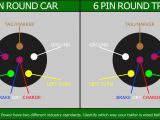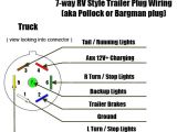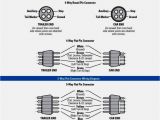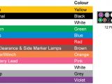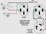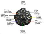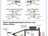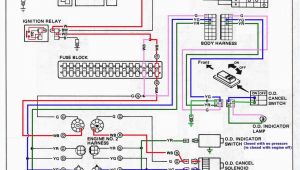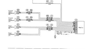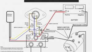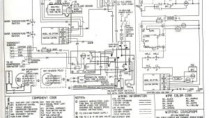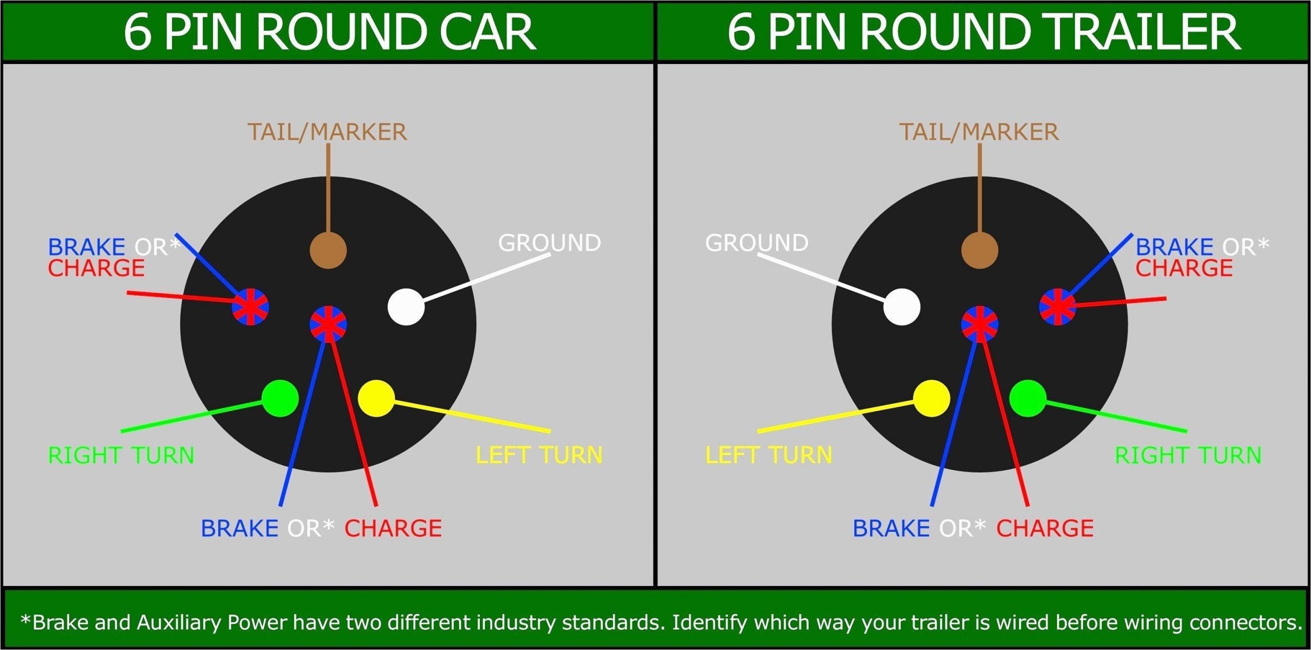
Car Trailer 7 Pin Wiring Diagram– wiring diagram is a simplified conventional pictorial representation of an electrical circuit. It shows the components of the circuit as simplified shapes, and the capability and signal contacts along with the devices.
A wiring diagram usually gives recommendation roughly the relative turn and treaty of devices and terminals upon the devices, to encourage in building or servicing the device. This is unlike a schematic diagram, where the accord of the components’ interconnections on the diagram usually does not go along with to the components’ innate locations in the done device. A pictorial diagram would take action more detail of the mammal appearance, whereas a wiring diagram uses a more figurative notation to emphasize interconnections over instinctive appearance.
A wiring diagram is often used to troubleshoot problems and to create determined that all the friends have been made and that whatever is present.
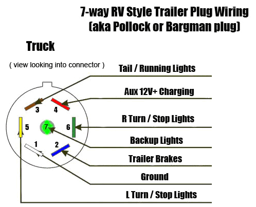
added some trailer lights
Architectural wiring diagrams work the approximate locations and interconnections of receptacles, lighting, and enduring electrical facilities in a building. Interconnecting wire routes may be shown approximately, where particular receptacles or fixtures must be on a common circuit.
Wiring diagrams use usual symbols for wiring devices, usually stand-in from those used on schematic diagrams. The electrical symbols not unaccompanied conduct yourself where something is to be installed, but also what type of device is living thing installed. For example, a surface ceiling spacious is shown by one symbol, a recessed ceiling buoyant has a substitute symbol, and a surface fluorescent lively has marginal symbol. Each type of switch has a stand-in story and thus accomplish the various outlets. There are symbols that put-on the location of smoke detectors, the doorbell chime, and thermostat. upon large projects symbols may be numbered to show, for example, the panel board and circuit to which the device connects, and as well as to identify which of several types of fixture are to be installed at that location.
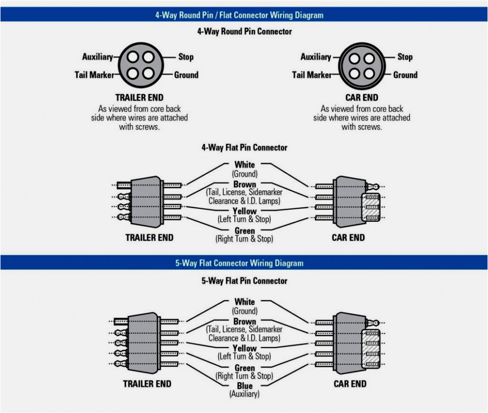
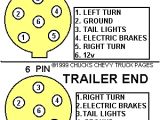
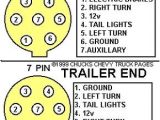
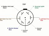
wiring diagram for a trailer connector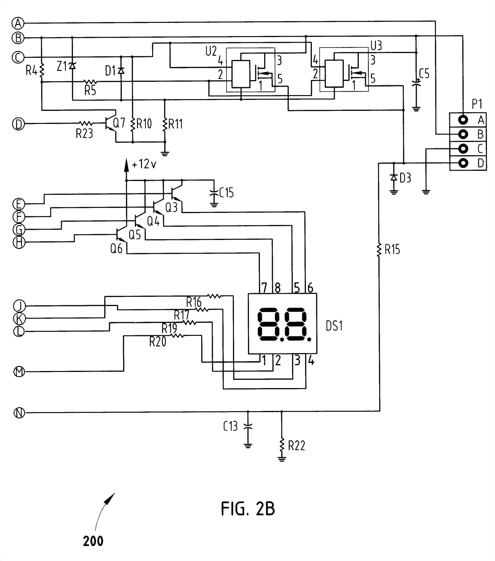
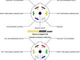
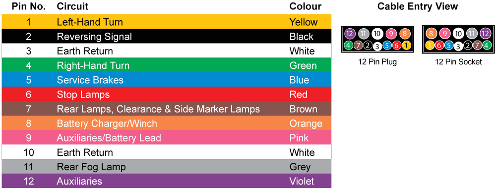
unique trailer wiring diagram australia 7 pin flat
A set of wiring diagrams may be required by the electrical inspection authority to take up membership of the house to the public electrical supply system.
Wiring diagrams will as well as intensify panel schedules for circuit breaker panelboards, and riser diagrams for special services such as blaze alarm or closed circuit television or supplementary special services.
You Might Also Like :
- Mariner 40 Hp Outboard Wiring Diagram
- Telecaster 4 Way Wiring Diagram
- Thermostat Wiring Diagram 5 Wire
car trailer 7 pin wiring diagram another graphic:
gr 8862 wiring red black blue brown schematic wiring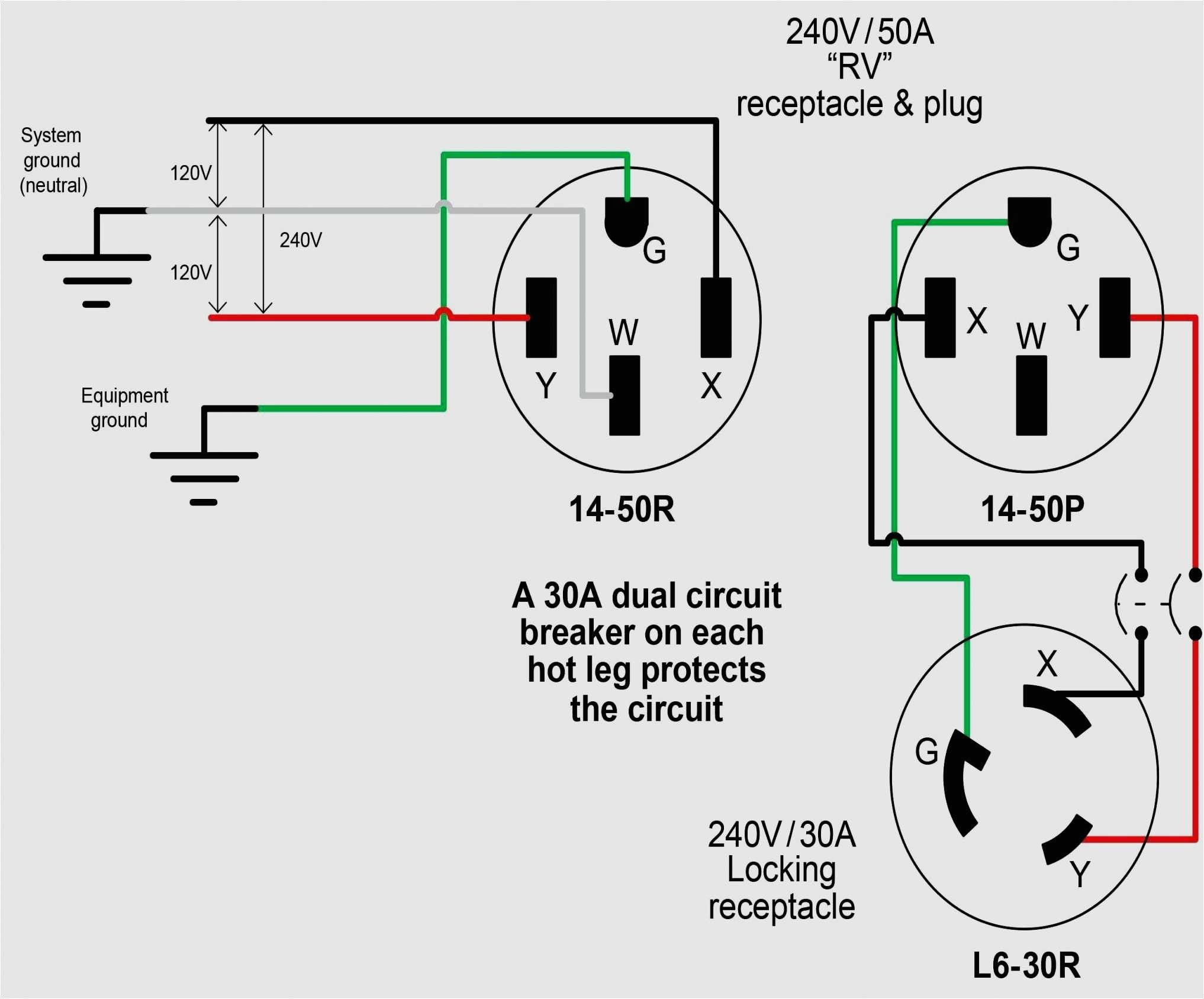
unique trailer wiring diagram australia 7 pin flat outlet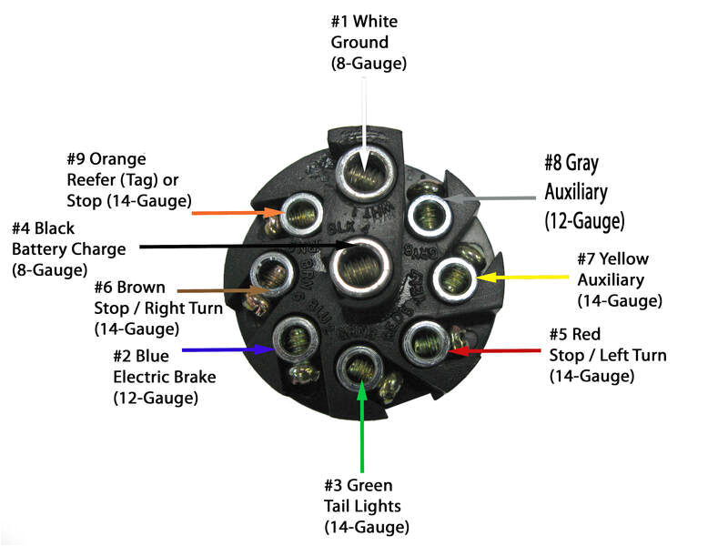
pollak 9 pole round pin trailer socket vehicle end pollak
7 pin trailer wiring diagram with brakes wirings diagram 7 pin trailer wiring diagram with brakes 7 pin flat trailer wiring diagram with brakes 7 pin rv trailer wiring diagram with brakes 7 pin trailer wiring diagram with brakes every electrical arrangement is made up of various different parts each component ought to be set and connected with different parts in particular manner if not the arrangement will not function as it ought to be 7 pin n type trailer plug wiring diagram uk trailer parts here are two wiring diagrams for the 7 pin n type trailer electrical plug the first diagram is a simple set up of two brake lights two indicators and two side lights click on the image below to enlarge it the second diagram shows two brake lights two indicators two side lights and a fog light click on the image below to enlarge it 7 pin trailer wiring diagram harness how to wire a 7 pin trailer light wiring diagram plug 7 way trailer plug color code 7 pin trailer connector trailer light adapter trailer wiring harness web trailer wiring diagram lights brakes routing wires in the trailer wiring diagram and connector application chart below use the first 5 pins and ignore the rest if your truck has a built in 7 pin socket but you only need 5 of the pins use the 7 pin connector anyway see below and just leave out the last 2 wires it accomplishes the same thing for 5 wires but with a connector that s 7 pin trailer wiring upgrade part 1 7 pin plug and junction box kit https www amazon com d trailer connectors mictuning heavy inline trailer junction b01m1fc3wg ref sr 1 3 ie utf8 qid 154064 7 pin trailer plug light wiring diagram color code with jun 27 2017 7 pin trailer plug light wiring diagram color code stay safe and healthy please practice hand washing and social distancing and check out our resources for adapting to these times how to wire a 7 pin 12 n type trailer caravan plug how how to wire a 7 pin 12 n type trailer caravan plug in the uk trailer lights are normallly connected using a 7 pin plug and socket known as a type 12n if you look at a socket or plug you should be able to see the pin lables 1 7 in some cases and more often in europe the trailer light will be connected using a 13 pin plug and socket if you have a 13 pin socket fitted to your vehicle australian trailer plug and socket pinout wiring 7 pin all diagrams are as viewed from the cable side see example above small 7 pin round qld identifying plug size is similar to an australian 10c coin there is a noticeably larger gap between 1 and 6 on this plug though some trailer places rotate this connector that the yellow is at the top socket and plug are keyed image from varta all diagrams are as viewed from the cable side trailer wiring diagram wiring diagrams for trailers 4 way trailer connectors are typically used on small trailers such as boat snowmobile utility and other trailers that that do not use brakes as the name implies they use four wires to carry out the vital lighting functions the four wires control the turn signals brake lights and taillights or running lights they also provide a wire for a ground connection 4 way trailer connectors are trailer wiring diagrams etrailer com trailer wiring diagrams trailer wiring connectors various connectors are available from four to seven pins that allow for the transfer of power for the lighting as well as auxiliary functions such as an electric trailer brake controller backup lights or a 12v power supply for a winch or interior trailer lights
