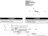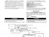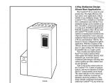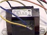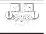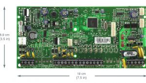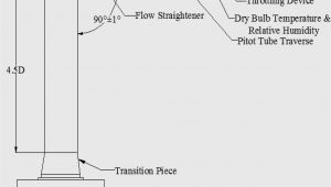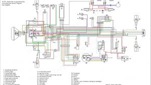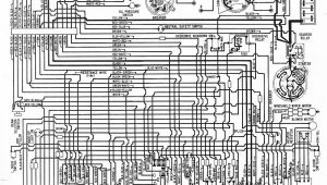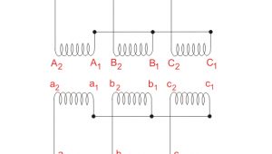
Carrier 3 Wire Pilot assembly Wiring Diagram– wiring diagram is a simplified good enough pictorial representation of an electrical circuit. It shows the components of the circuit as simplified shapes, and the capacity and signal contacts in the midst of the devices.
A wiring diagram usually gives counsel nearly the relative perspective and settlement of devices and terminals on the devices, to back in building or servicing the device. This is unlike a schematic diagram, where the union of the components’ interconnections upon the diagram usually does not see eye to eye to the components’ bodily locations in the done device. A pictorial diagram would feign more detail of the physical appearance, whereas a wiring diagram uses a more figurative notation to put the accent on interconnections higher than physical appearance.
A wiring diagram is often used to troubleshoot problems and to create clear that every the connections have been made and that all is present.
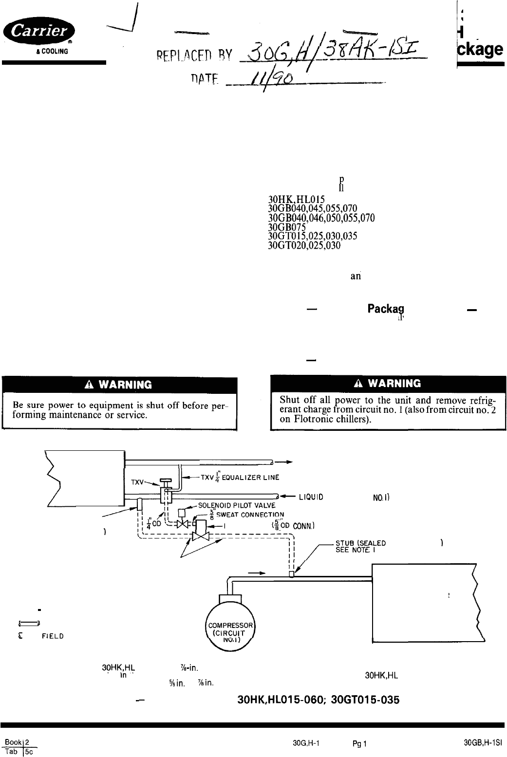
carrier 30gt users manual
Architectural wiring diagrams operate the approximate locations and interconnections of receptacles, lighting, and permanent electrical facilities in a building. Interconnecting wire routes may be shown approximately, where particular receptacles or fixtures must be upon a common circuit.
Wiring diagrams use customary symbols for wiring devices, usually every second from those used on schematic diagrams. The electrical symbols not by yourself produce a result where something is to be installed, but with what type of device is mammal installed. For example, a surface ceiling lighthearted is shown by one symbol, a recessed ceiling open has a swing symbol, and a surface fluorescent spacious has choice symbol. Each type of switch has a vary symbol and for that reason realize the various outlets. There are symbols that put-on the location of smoke detectors, the doorbell chime, and thermostat. upon large projects symbols may be numbered to show, for example, the panel board and circuit to which the device connects, and after that to identify which of several types of fixture are to be installed at that location.
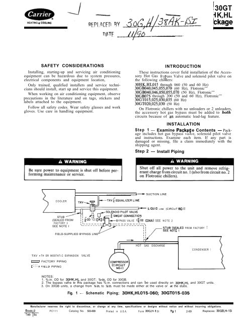
30gt k hl ckage carrier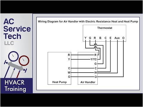
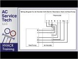
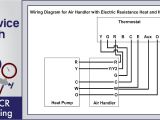
thermostat wiring diagrams 10 most common youtube
A set of wiring diagrams may be required by the electrical inspection authority to approve link of the domicile to the public electrical supply system.
Wiring diagrams will along with augment panel schedules for circuit breaker panelboards, and riser diagrams for special facilities such as fire alarm or closed circuit television or further special services.
You Might Also Like :
- 2007 Dodge Ram Radio Wiring Diagram
- Les Paul Electric Guitar Wiring Diagram
- Infinity Radio Wiring Diagram
carrier 3 wire pilot assembly wiring diagram another picture:
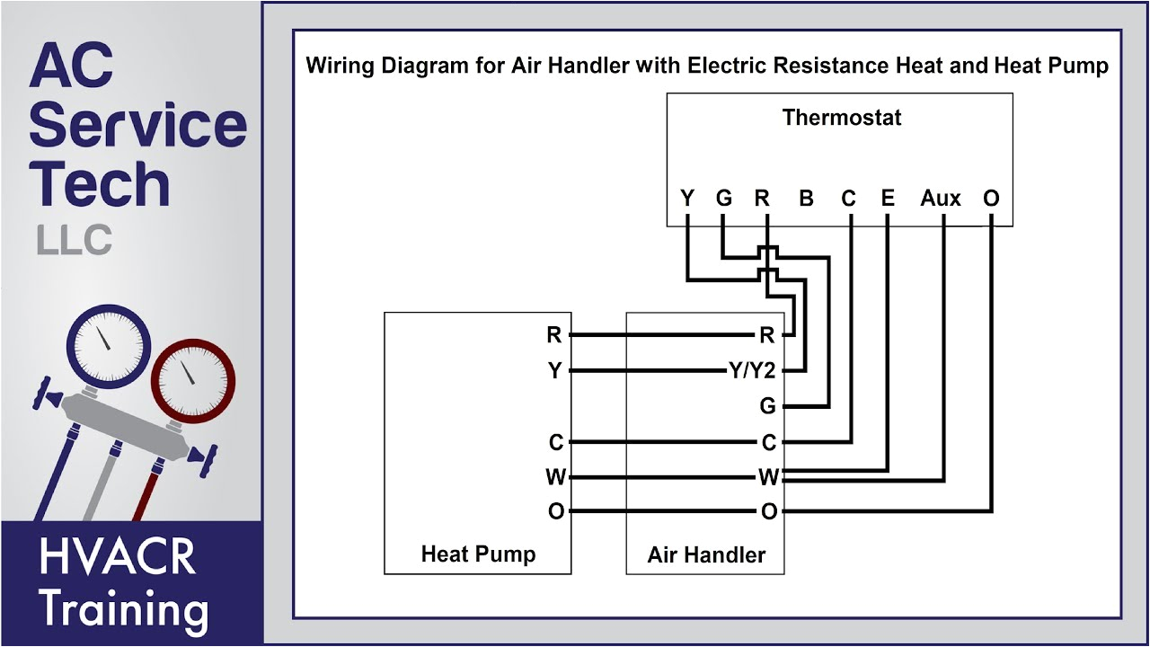
thermostat wiring diagrams 10 most common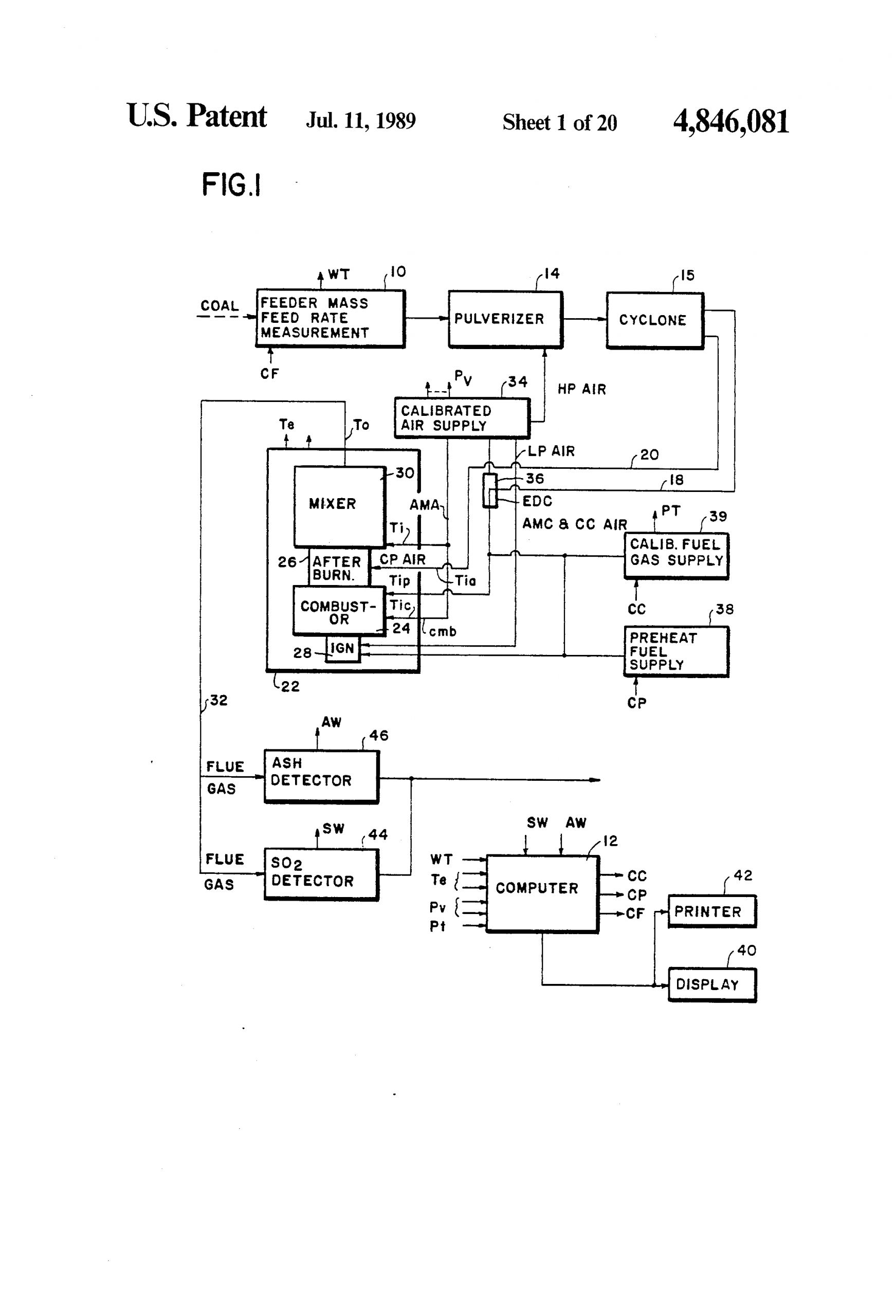
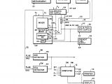
us4846081a calorimetry system google patents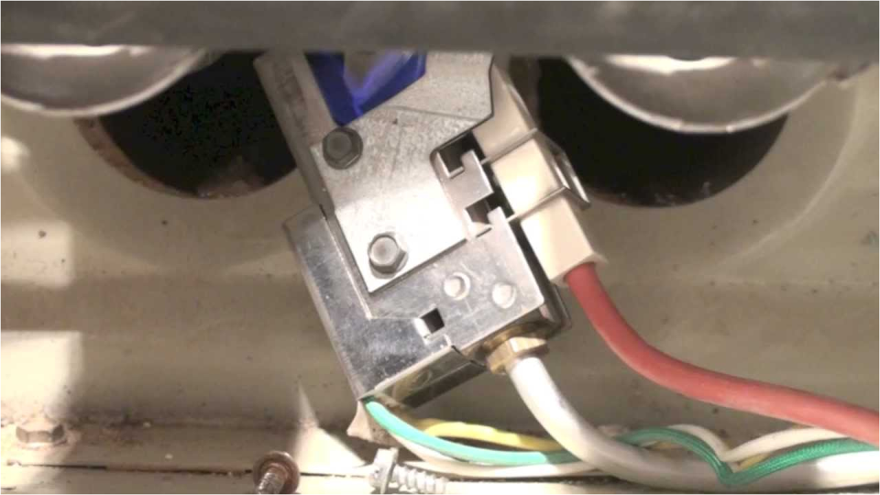
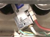
gas furnace ignition controls gray furnaceman furnace
carrier 58ss 58gp 3 wire pilot assembly operation i describe the operation of this 3 wire intermittent pilot assembly and some problems associated with it this is also the pilot for the 394 gaw and gau bryant day night payne this video is part old carrier furnace 3 wire pilot assembly electrode our 29 year old carrier furnace relies on a 3 wire pilot with an intermittent spark igniter it sparks probably around 30 times before the gas valve opens and the furnace fires up that s a lot of sparking and surely not good in and of itself but the real problem is it just keeps on sparking continually throughout the cycle up until exactly the moment when the blower stops 3 wire pilot replacement carrier furnace 1980 3 wire pilot replacement carrier furnace 1980 carrier 58gs furnace pilot assembly replacement duration 4 29 northsidevideo 2 286 views 4 29 carrier 58ss 58gp 3 wire pilot assembly problem fyi troubleshooting and cleaning a bryant carrier we sell the bryant carrier 3 wire pilot assembly on the following page https hi david i am sorry we do not have wiring diagrams for furnaces your furnace should have a wiring diagram attached to the furnace blower door or some where on the furnace body sorry that i can not help you out with a wiring diagram steve reply jay a watson december 24 2017 thank you i had worked out carrier three wire pilots google groups can anyone give me any insight into the normal operation of a carrier three wire pilot assembly was recently replaced with a new pilot because it would not prove pilot flame and thus burner would not fire i believe it is supossed to cut out spark after pilot flame is proven burner is now operating but spark ignitor is not cutting out thanks in advance john taylor carrier three wire need instructions for replacing the lh680005 3 wire pilot now screw the pilot tubing nut back on the new 3 wire pilot and make sure it goes in the same direction as the old one did then tighten put the high voltage lead back on the electrode and remount the pilot assembly with the 2 screws taken out earlier tight the pilot tubing back on the gas valve and hook up the wiring harness now you can test 394gaw 58gs sequence of operation the emphasis is on low voltage controls including the 3 wire pilot assembly a diagram is shown with the actual furnace to help show how it looks and works a diagram is shown with the actual ce lh680005 bryant carrier 3 wire pilot burner amazon com ce lh680005 bryant carrier 3 wire pilot burner 3 wire pilot burner assembly includes spark ignition replaces lh680005 for use with carrier day night bryant payne funaces 1 0 out of 5 stars 1 79 99 oem carrier furnace ignitor igniter electrode lh680512 5 0 out of 5 stars 2 64 78 fls0005 pilot burner and igniter replacement for carrier lh680005 5 0 out of 5 stars 2 147 99 troubleshoot electric pilot carrier bdp this pilot assembly was used on many carrier bdp units including carrier 58gp 58gs 58gsc 58ssb 58sx bryant day night payne 394gad 394gaw 394jaw 395baw wiring diagrams dms hvacpartners com wiring diagrams index unit 50byn v ph hz label diagram fig number 006 008 208 230 3 60 460 3 60 11720011 c 1 575 3 60 012 208 230 3 60 014 460 3 60 11720960 b 2 016 575 3 60 024 208 230 3 60 460 3 60 1172007 c 3 575 3 60 accessory wiring unit 50byn accessory description fig number 006 024 winter start 4 evaporator defrost thermostat 5 temp thermostat 6 variable volume and temperature vvtt
