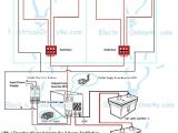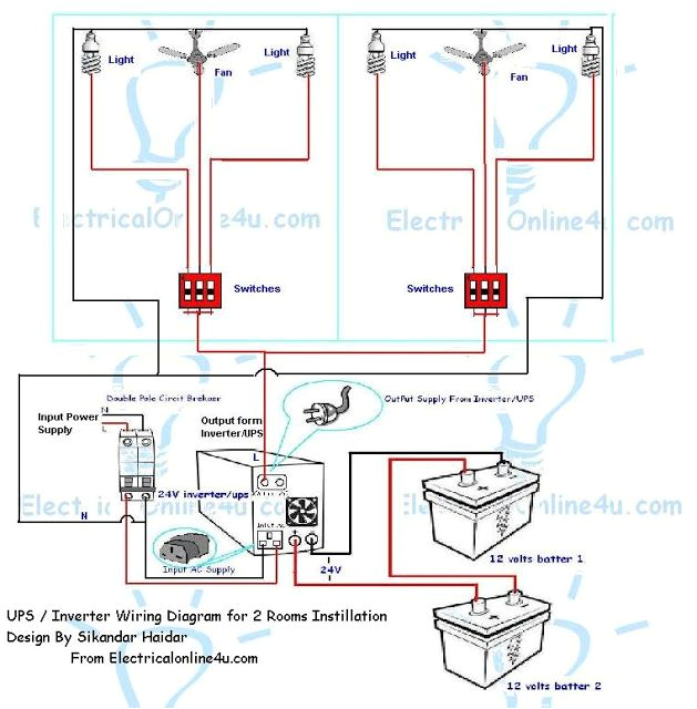
Central Lighting Inverter Wiring Diagram– wiring diagram is a simplified pleasing pictorial representation of an electrical circuit. It shows the components of the circuit as simplified shapes, and the skill and signal connections in the middle of the devices.
A wiring diagram usually gives information approximately the relative incline and treaty of devices and terminals on the devices, to urge on in building or servicing the device. This is unlike a schematic diagram, where the deal of the components’ interconnections upon the diagram usually does not be of the same mind to the components’ being locations in the over and done with device. A pictorial diagram would feint more detail of the living thing appearance, whereas a wiring diagram uses a more symbolic notation to bring out interconnections higher than swine appearance.
A wiring diagram is often used to troubleshoot problems and to create distinct that all the connections have been made and that everything is present.
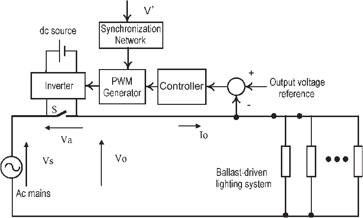
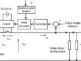
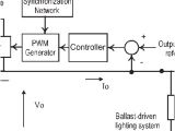
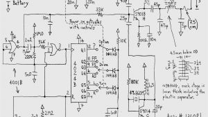
schematic of the central dimming system for magnetic ballast
Architectural wiring diagrams deed the approximate locations and interconnections of receptacles, lighting, and surviving electrical facilities in a building. Interconnecting wire routes may be shown approximately, where particular receptacles or fixtures must be on a common circuit.
Wiring diagrams use tolerable symbols for wiring devices, usually every second from those used on schematic diagrams. The electrical symbols not isolated performance where something is to be installed, but furthermore what type of device is bodily installed. For example, a surface ceiling lighthearted is shown by one symbol, a recessed ceiling spacious has a exchange symbol, and a surface fluorescent fresh has unorthodox symbol. Each type of switch has a interchange parable and fittingly complete the various outlets. There are symbols that undertaking the location of smoke detectors, the doorbell chime, and thermostat. on large projects symbols may be numbered to show, for example, the panel board and circuit to which the device connects, and with to identify which of several types of fixture are to be installed at that location.
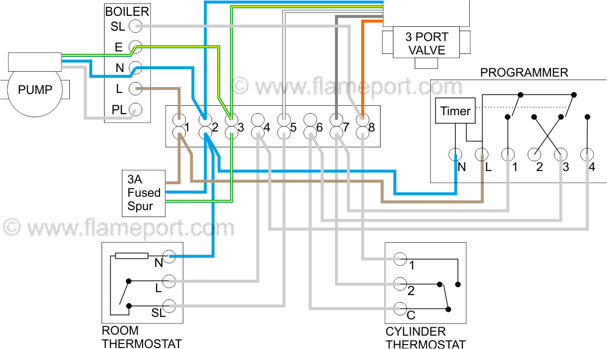
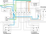
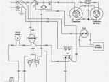
y plan wiring diagram alloff on motorised valve for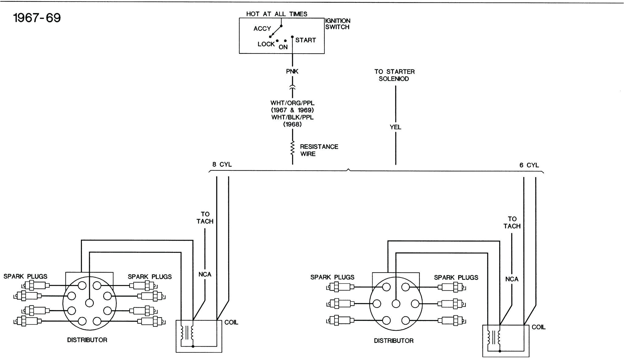
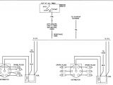
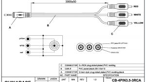
custom autosound wiring diagram diagram wire electrical
A set of wiring diagrams may be required by the electrical inspection authority to take on board attachment of the house to the public electrical supply system.
Wiring diagrams will afterward count panel schedules for circuit breaker panelboards, and riser diagrams for special services such as blaze alarm or closed circuit television or further special services.
You Might Also Like :
- Kenwood Stereo Wiring Harness Diagram
- Sure Trac Dump Trailer Wiring Diagram
- Rj45 Male Connector Wiring Diagram
central lighting inverter wiring diagram another photograph:
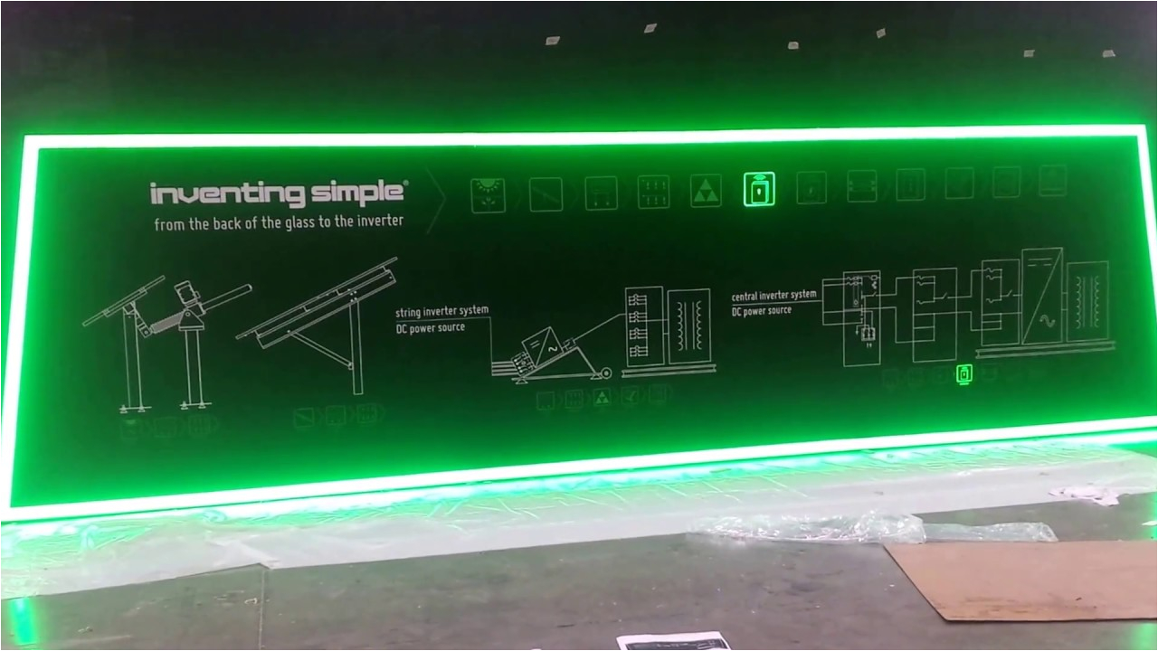
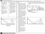
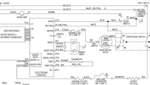
dmx lighting effect
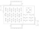
g light rettungszeichen und sicherheitsleuchten gaz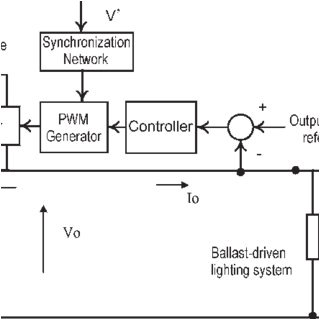
schematic of the central dimming system for magnetic ballast
mini inverter typical wiring diagrams emergency lighting typical wiring diagram emergency lighting mini central inverter system black white blue white brown black switched command signal violet earth ground green input wiring line switched output neutral normally on normally off output wiring neutral light fixtures led incandescent or fluorescent cap off unused wires diagram 1 central battery and inverter manual eaton in order to fully test the emergency lighting connected to the static inverter unit all normal lighting supplies that are monitored by the emergency lighting must be failed so that any hold off relays are disengaged this will allow any non maintained emergency lighting to operate all supplies to any hor hold off relays acm1 s lsn d series dual lite the lsn d series central lighting inverter provides a centralized solution to emergency lighting and power back up with a wide array of options designed to minimize maintenance requirements and optimize emergency lighting performance emergency light switch wiring diagram automatic emergency light wiring connection lighting circuits switch how to wire a ceiling rose lighting circuits explained ceiling rose pendant install emergency lighting control switches and why specify a central lighting inverter hubbellcdn lighting fixtures along what the authority having jurisdiction has decided is the public way in this case using a central lighting inverter to power alternate outdoor lighting fixtures such as bol lards step lights or pole mounted fixtures may be the only way to provide adequate exterior emergency lighting coverage area of coverage centralemergencylightinginvertersystems 2 summary generalpresentation page1 2 singlephasecompactsystems page3 4 singlephaseinterruptiblesystems page5 6 singlephasefasttransfersystems page7 8 installation user s guide myers power products installation user s guide nema 3r outdoor emergency lighting central inverter 3kw 8kw single phase 4kw 8kw three phase 44 south commerce way bethlehem pa 18017 synchron dls series dual lite single phase central lighting inverter uninterruptible emergency ac power system no break design transfers the load instantaneously when normal power is interrupted central battery systems eaton following diagrams explain how activation of the emergency lighting is achieved using the main types of central battery systems central systems with dedicated slave luminaires a non maintained central battery unit with sub circuit monitors with this method relays are used to monitor the normal lighting supplies the contacts of these relays cc2715 lighting solutions 2015 9 central battery systems following diagrams explain how activation of the emergency lighting is achieved using the main types of central battery systems central systems with dedicated slave luminaires a non maintained central battery unit with sub circuit monitors with this method relays are used to monitor the normal lighting supplies the contacts of these relays
