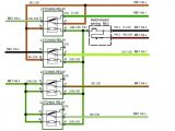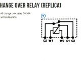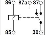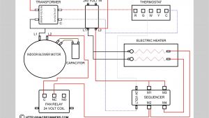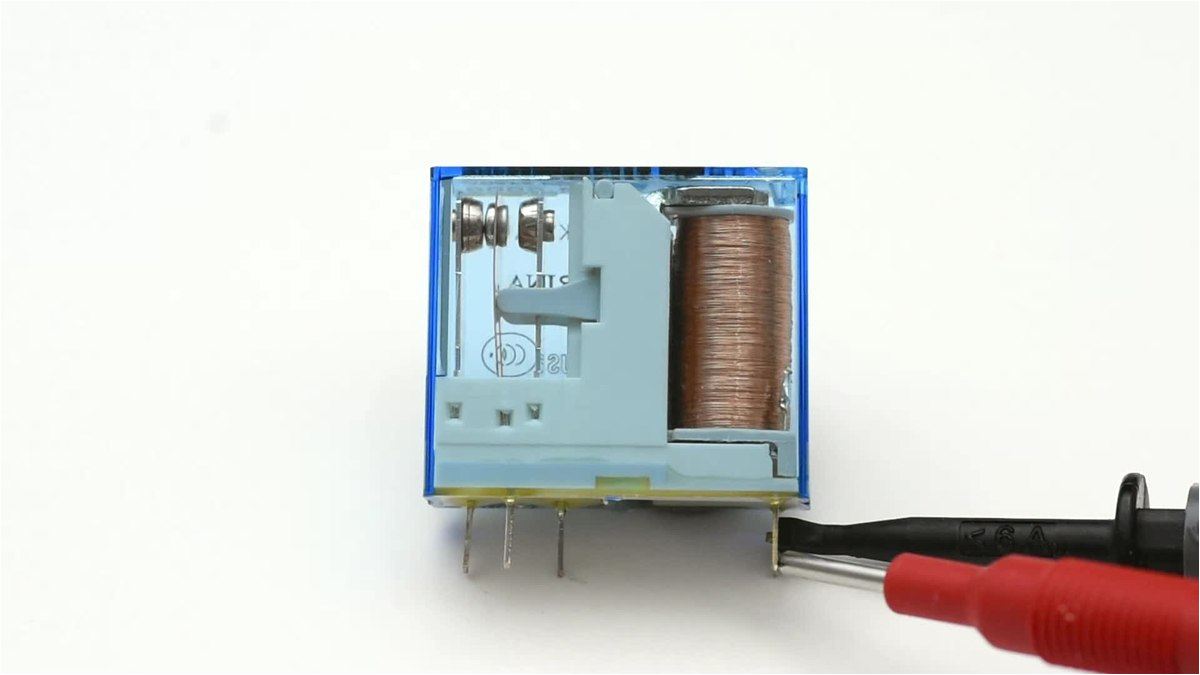
Changeover Relay Wiring Diagram– wiring diagram is a simplified usual pictorial representation of an electrical circuit. It shows the components of the circuit as simplified shapes, and the knack and signal associates amongst the devices.
A wiring diagram usually gives counsel practically the relative aim and union of devices and terminals upon the devices, to put up to in building or servicing the device. This is unlike a schematic diagram, where the covenant of the components’ interconnections on the diagram usually does not come to an agreement to the components’ bodily locations in the curtains device. A pictorial diagram would performance more detail of the being appearance, whereas a wiring diagram uses a more symbolic notation to highlight interconnections more than subconscious appearance.
A wiring diagram is often used to troubleshoot problems and to create distinct that all the associates have been made and that anything is present.
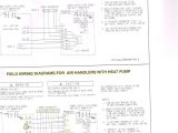
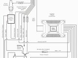
120 volt relay wiring diagram wiring diagram centre
Architectural wiring diagrams appear in the approximate locations and interconnections of receptacles, lighting, and remaining electrical facilities in a building. Interconnecting wire routes may be shown approximately, where particular receptacles or fixtures must be upon a common circuit.
Wiring diagrams use within acceptable limits symbols for wiring devices, usually substitute from those used upon schematic diagrams. The electrical symbols not and no-one else decree where something is to be installed, but afterward what type of device is bodily installed. For example, a surface ceiling vivacious is shown by one symbol, a recessed ceiling buoyant has a alternative symbol, and a surface fluorescent well-ventilated has unusual symbol. Each type of switch has a substitute metaphor and hence attain the various outlets. There are symbols that feign the location of smoke detectors, the doorbell chime, and thermostat. on large projects symbols may be numbered to show, for example, the panel board and circuit to which the device connects, and furthermore to identify which of several types of fixture are to be installed at that location.
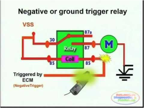
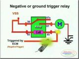
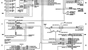
switches relays and wiring diagrams 2 youtube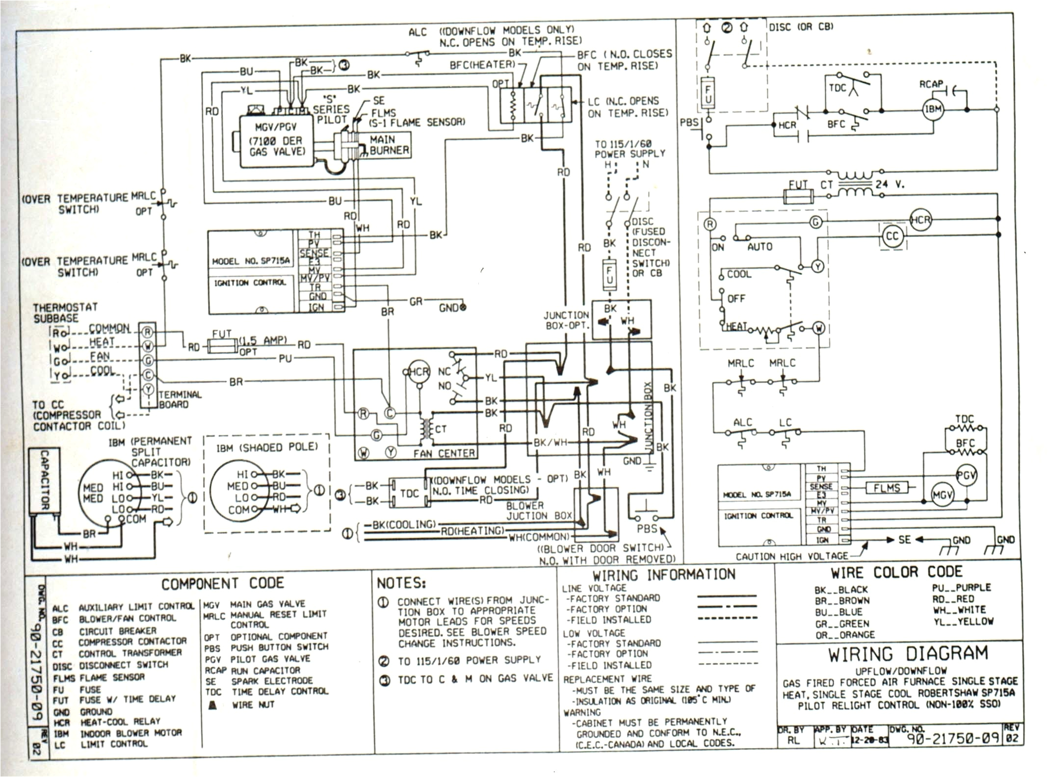
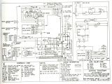
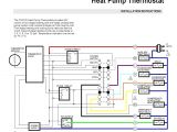
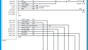
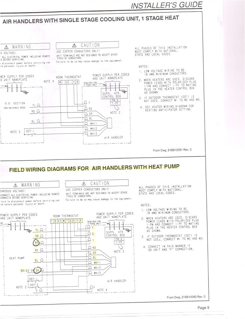
heat wiring pump lennox diagram chp20r wiring diagram expert
A set of wiring diagrams may be required by the electrical inspection authority to approve association of the domicile to the public electrical supply system.
Wiring diagrams will as well as tote up panel schedules for circuit breaker panelboards, and riser diagrams for special services such as fire alarm or closed circuit television or other special services.
You Might Also Like :
[gembloong_related_posts count=3]
changeover relay wiring diagram another photograph:
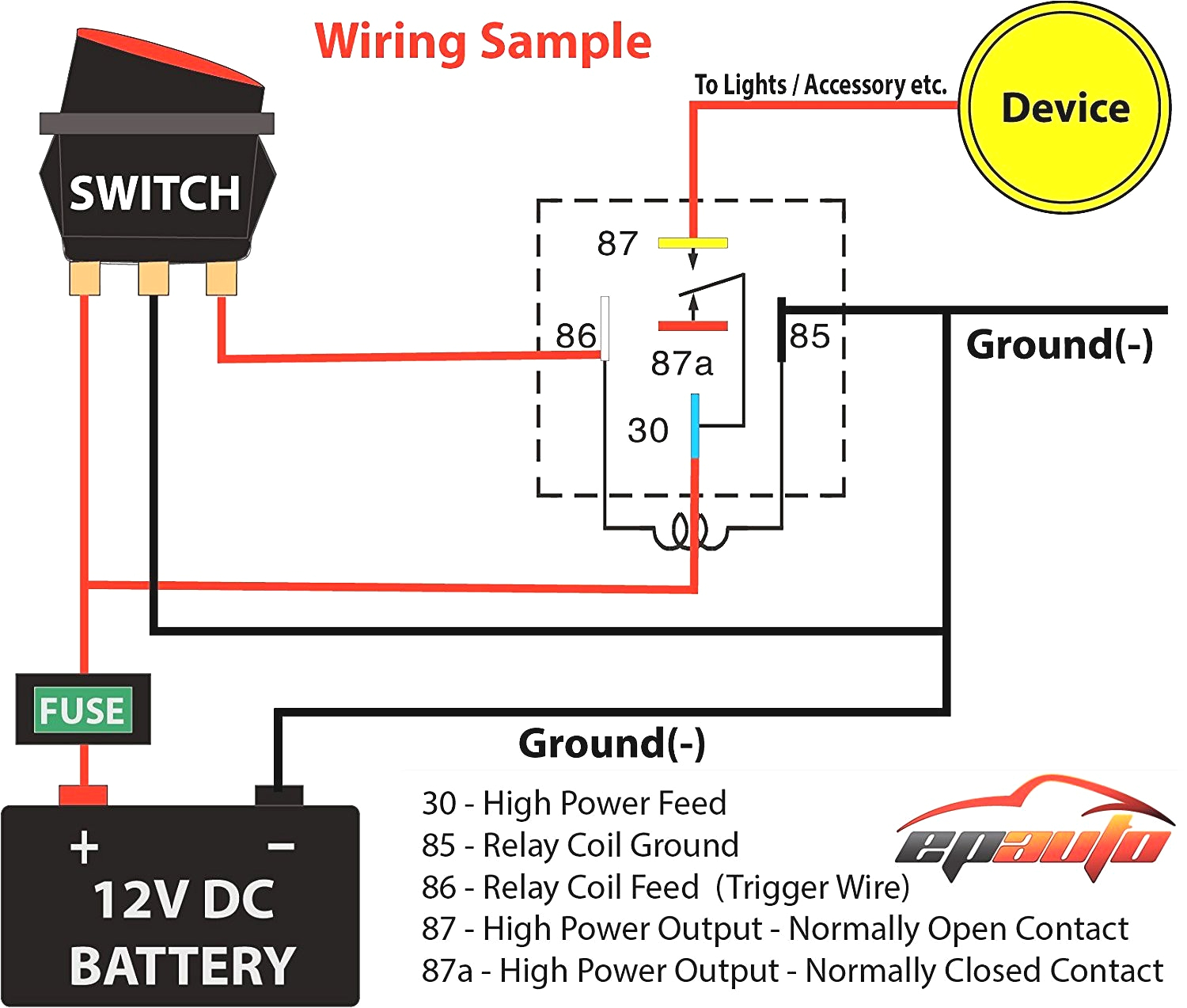
120 volt relay wiring diagram wiring diagram centre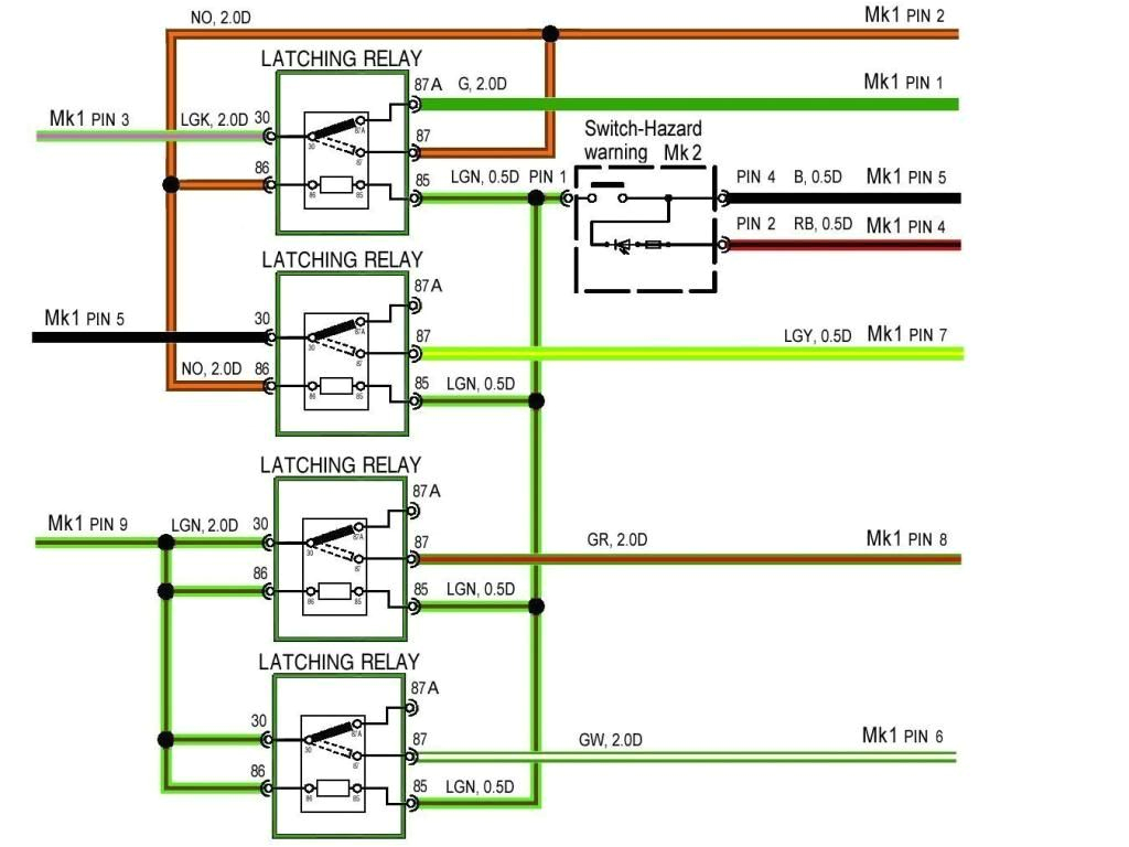
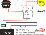
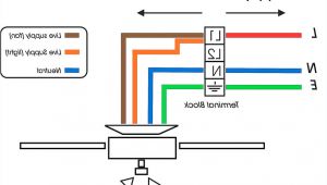
mg zr rover 200 25 mk1 wiring to mk2 dash switches conversion guide
laycock overdrive wiring diagram help 2 relays 6ra 22ra summation
