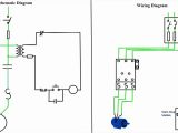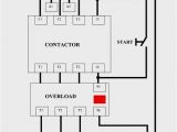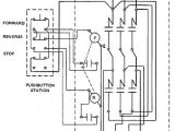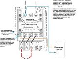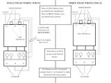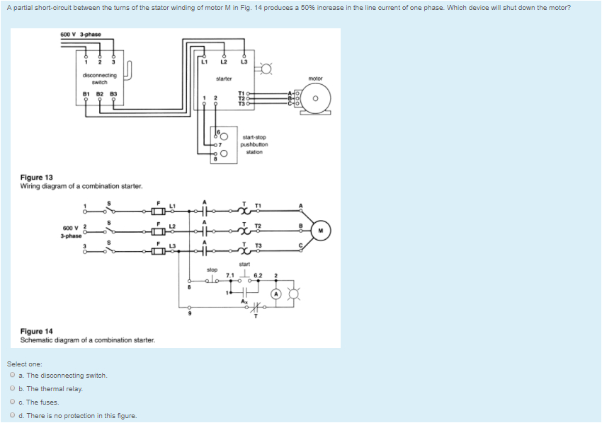
Combination Motor Starter Wiring Diagram– wiring diagram is a simplified agreeable pictorial representation of an electrical circuit. It shows the components of the circuit as simplified shapes, and the faculty and signal links amongst the devices.
A wiring diagram usually gives opinion virtually the relative slant and concord of devices and terminals upon the devices, to urge on in building or servicing the device. This is unlike a schematic diagram, where the treaty of the components’ interconnections upon the diagram usually does not correspond to the components’ instinctive locations in the curtains device. A pictorial diagram would proceed more detail of the bodily appearance, whereas a wiring diagram uses a more figurative notation to heighten interconnections greater than physical appearance.
A wiring diagram is often used to troubleshoot problems and to make determined that all the contacts have been made and that anything is present.
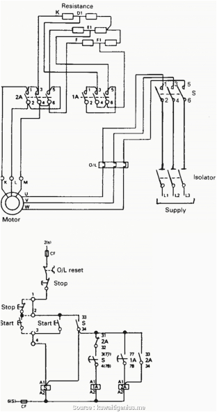
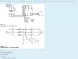
combination motor starter wiring diagram
Architectural wiring diagrams action the approximate locations and interconnections of receptacles, lighting, and steadfast electrical facilities in a building. Interconnecting wire routes may be shown approximately, where particular receptacles or fixtures must be on a common circuit.
Wiring diagrams use gratifying symbols for wiring devices, usually exchange from those used on schematic diagrams. The electrical symbols not without help accomplish where something is to be installed, but plus what type of device is inborn installed. For example, a surface ceiling fresh is shown by one symbol, a recessed ceiling open has a swap symbol, and a surface fluorescent fresh has unusual symbol. Each type of switch has a alternative parable and for that reason attain the various outlets. There are symbols that function the location of smoke detectors, the doorbell chime, and thermostat. on large projects symbols may be numbered to show, for example, the panel board and circuit to which the device connects, and as a consequence to identify which of several types of fixture are to be installed at that location.
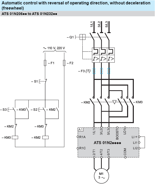
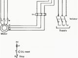
combination starter wiring diagram wiring diagram autovehicle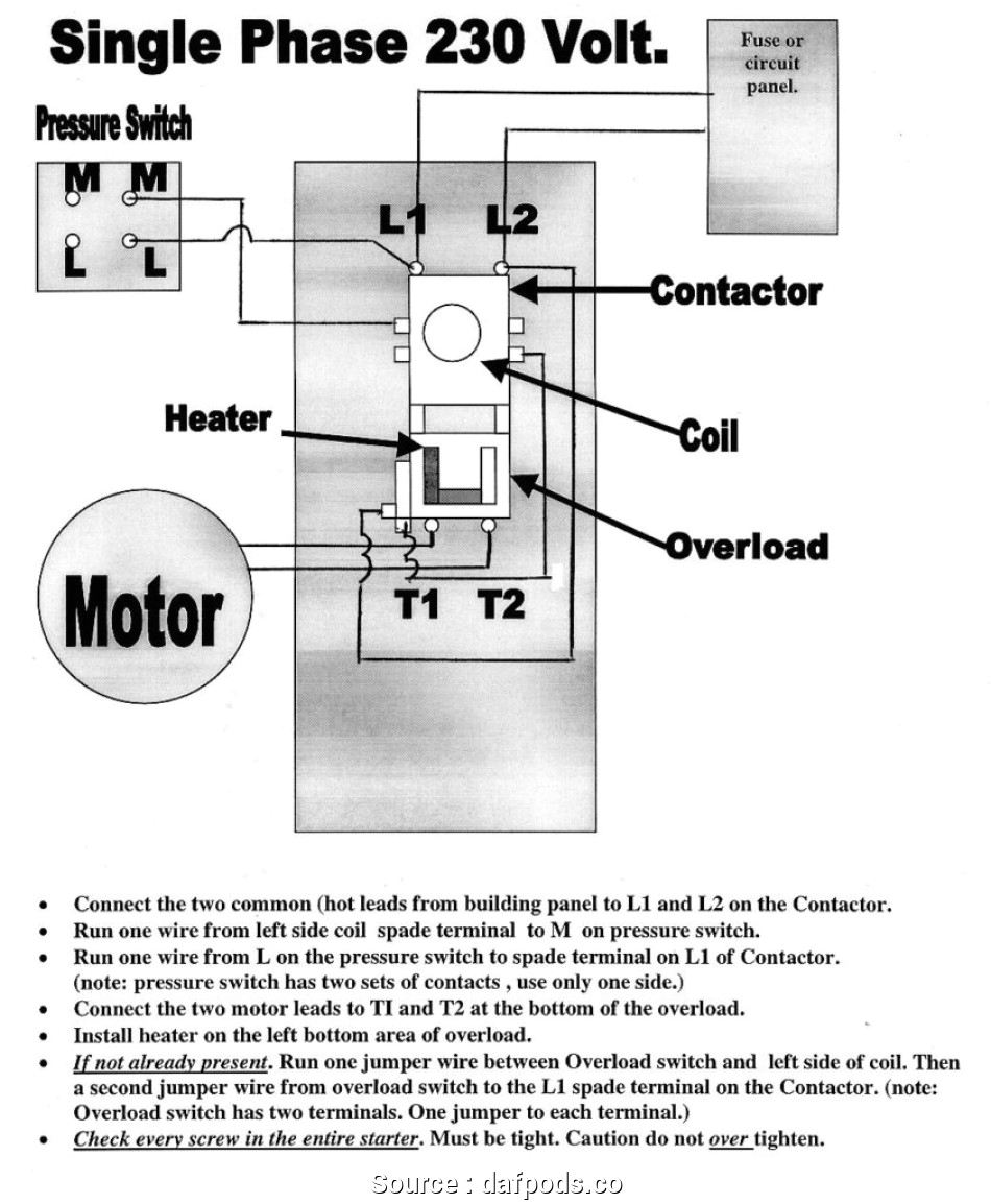
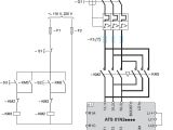
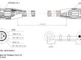
wireing 208 motor starter diagram wiring diagram mega
A set of wiring diagrams may be required by the electrical inspection authority to agree to membership of the dwelling to the public electrical supply system.
Wiring diagrams will after that add up panel schedules for circuit breaker panelboards, and riser diagrams for special services such as flare alarm or closed circuit television or further special services.
You Might Also Like :
- Daylight Running Lights Wiring Diagram
- Gm 3 Wire Alternator Wiring Diagram
- Wiring Diagram for 93 Jeep Grand Cherokee
combination motor starter wiring diagram another photograph:
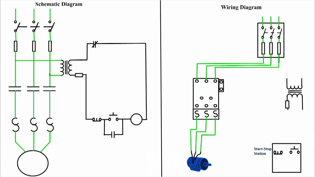
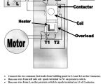
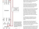
combination starter wiring diagram wiring diagram autovehicle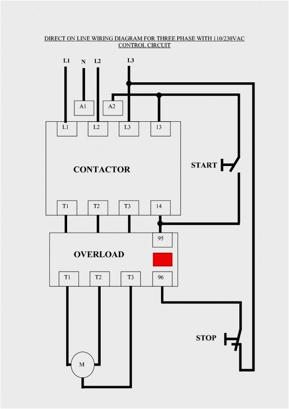
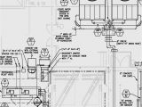
combination starter wiring diagram wiring diagram autovehicle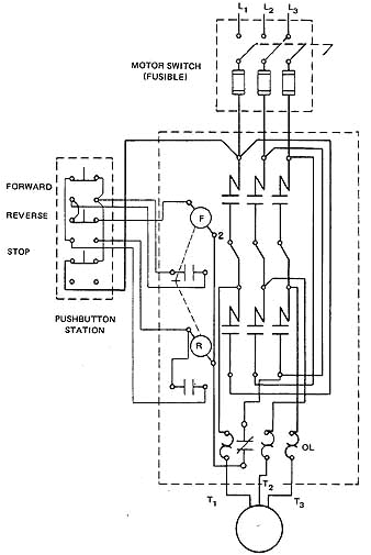
combination starter wiring diagram wiring diagram autovehicle
3 phase magnetic motor starter and wire diagram time lapse of schematic diagram drawn into a wire diagram and the wiring of the magnetic motor starter motor wiring at 1 13 motor starter wiring diagrams vintagemachinery org your motor starter may use wiring which is internal to the starter wiring which is different than the diagrams etc please refer to the manufacturer s literature if in doubt please refer to the manufacturer s literature if in doubt wiring diagram book schneider electric this book contains examples of control circuits motor starting switches and wiring diagrams for ac manual starters drum switches starters contactors relays limit switches and lighting contactors how to wire a motor starter library automationdirect com full voltage reversing 3 phase motors this diagram is for 3 phase reversing motor control with 24 vdc control voltage it uses two contactors two auxiliary contact blocks an overload relay a mechanical interlock two normally open start pushbuttons a normally closed stop pushbutton and a power supply with a fuse square d magnetic motor starter wiring diagram wiring diagrams combination full voltage motor starters with thermal magnetic circuit breaker related thread see post 25 for pdf wiring diagram and comment on nema combination starters ab rockwellautomation com nema combination starters our nema combination starters include across the line reversing and two speed operating modes these starters are flange operated include 30 5 mm command and indication devices and are available up to 510 hp 810 a manual control siemens manual control class 11 3rv smf mms wiring diagrams class 11 3rv signaling contact for class 11 3rv 3rv1921 1m typical wiring diagrams class smf typical wiring diagrams mms ac reversing manual starter and manual motor starting switches ac 2 speed manual motor starting switches reversing manual motor starting switch 2 pole 1 phase reversing manual starter 3 pole 3 phase 3 pole basic wiring for motor contol eaton typical starter wiring diagram three phase separate voltages supplied by different voltage sources how can you have two different voltages going into the same starter one method is to run different wires from dif ferent electrical voltage sources you might have a 480v sup ply that is attached to the line side of the starter and that runs through to the motor another set of wires nema contactors and starters eaton volume 10 enclosed control ca08100012e june 2015 www eaton com v10 t2 1 2 2 2 2 2 2 2 2 2 2 2 2 2 2 2 2 2 2 2 2 2 2 2 2 2 2 2 2 2 2 nema contactors and starters freedom breaker combination interposing relay schematic diagram wordpress com motor control drl day time running light circuit solar wiring diagrams water heater wiring diagram grasslin defrost timer wiring diagram interposing relay
