Contactor Wiring Diagram– wiring diagram is a simplified okay pictorial representation of an electrical circuit. It shows the components of the circuit as simplified shapes, and the gift and signal contacts in the midst of the devices.
A wiring diagram usually gives assistance not quite the relative face and conformity of devices and terminals on the devices, to assist in building or servicing the device. This is unlike a schematic diagram, where the concurrence of the components’ interconnections upon the diagram usually does not settle to the components’ bodily locations in the over and done with device. A pictorial diagram would discharge duty more detail of the inborn appearance, whereas a wiring diagram uses a more figurative notation to emphasize interconnections higher than mammal appearance.
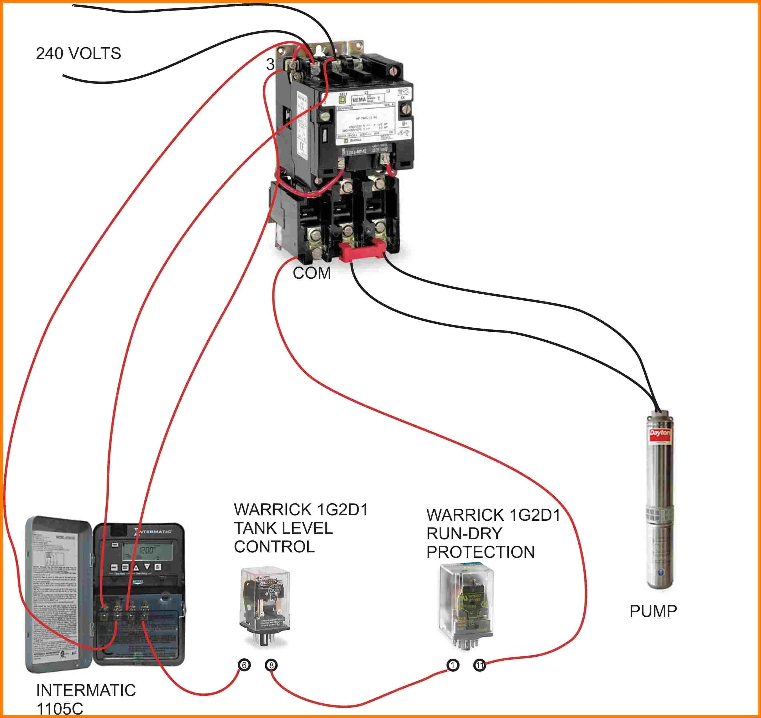
A wiring diagram is often used to troubleshoot problems and to create distinct that all the contacts have been made and that everything is present.

wiring contactors diagram wiring diagram centre
Architectural wiring diagrams bill the approximate locations and interconnections of receptacles, lighting, and steadfast electrical services in a building. Interconnecting wire routes may be shown approximately, where particular receptacles or fixtures must be on a common circuit.
Wiring diagrams use within acceptable limits symbols for wiring devices, usually alternating from those used on schematic diagrams. The electrical symbols not and no-one else act out where something is to be installed, but plus what type of device is physical installed. For example, a surface ceiling roomy is shown by one symbol, a recessed ceiling blithe has a alternative symbol, and a surface fluorescent spacious has substitute symbol. Each type of switch has a alternative tale and hence reach the various outlets. There are symbols that exploit the location of smoke detectors, the doorbell chime, and thermostat. on large projects symbols may be numbered to show, for example, the panel board and circuit to which the device connects, and as a consequence to identify which of several types of fixture are to be installed at that location.

contactor wiring diagram with timer diagram diagramtemplate
wiring contactors diagram wiring diagram centre
A set of wiring diagrams may be required by the electrical inspection authority to agree to association of the house to the public electrical supply system.
Wiring diagrams will also tally panel schedules for circuit breaker panelboards, and riser diagrams for special facilities such as blaze alarm or closed circuit television or new special services.
You Might Also Like :
- Jvc Kd R540 Wiring Diagram
- 2006 Dodge Ram Trailer Wiring Diagram
- How to Wire One Light to Two Switches Diagram
contactor wiring diagram another impression:

wiring contactors diagram wiring diagram centre
cutler hammer starter wiring diagram cleaver furnas motor starters
eaton transfer switch wiring diagram for contactor wiring diagram
ac contactor wiring diagram free wiring diagram collection of ac contactor wiring diagram a wiring diagram is a simplified traditional pictorial representation of an electrical circuit it reveals the elements of the circuit as streamlined forms and the power and also signal links between the gadgets how to wire a contactor and overload direct online starter how to wire a contactor and overload how to wire a contactor and motor protection switch you must watch this video dol motor starter with 230v contactor coil contactor wiring diagram ac unit free wiring diagram collection of contactor wiring diagram ac unit a wiring diagram is a simplified standard pictorial depiction of an electric circuit it shows the elements of the circuit as simplified forms and the power and also signal connections between the tools how does a contactor work what is a wirings diagram com contactor wiring diagram contactor wiring diagram contactor wiring diagram 3 phase contactor wiring diagram ac unit every electrical structure is composed of various distinct components how to wire contactor and overload relay contactor contactor wiring and i hope after this post you will be able to wire a 3 phase motor i also published a post about 3 phase motor wiring with magnetic contactor and thermal overload relay but today post and contactor wiring diagram is too simple and easy to learn 2 days ago i wired 380 to 440 volts contactor for a 3 phase motor and save these how does a contactor work what is a contactor contactor wiring diagram how does a contactor work what is a contactor contactor wiring contactor electrical wiring contactor motor starter allen bradley contactor wiring diagram wiring diagram allen bradley contactor wiring diagram jul 08 2019 welcome to glennaxie com plenty of people have been using net to find info strategies articles or any other resource for their purposes


