Double Pole Contactor Wiring Diagram– wiring diagram is a simplified okay pictorial representation of an electrical circuit. It shows the components of the circuit as simplified shapes, and the capability and signal links together with the devices.
A wiring diagram usually gives instruction not quite the relative direction and bargain of devices and terminals upon the devices, to help in building or servicing the device. This is unlike a schematic diagram, where the pact of the components’ interconnections upon the diagram usually does not reach agreement to the components’ physical locations in the ended device. A pictorial diagram would achievement more detail of the bodily appearance, whereas a wiring diagram uses a more symbolic notation to put the accent on interconnections higher than monster appearance.
A wiring diagram is often used to troubleshoot problems and to make definite that all the associates have been made and that all is present.

3 Pole Double Throw Contactor
Architectural wiring diagrams performance the approximate locations and interconnections of receptacles, lighting, and steadfast electrical services in a building. Interconnecting wire routes may be shown approximately, where particular receptacles or fixtures must be upon a common circuit.
Wiring diagrams use within acceptable limits symbols for wiring devices, usually every second from those used on schematic diagrams. The electrical symbols not lonesome perform where something is to be installed, but plus what type of device is creature installed. For example, a surface ceiling open is shown by one symbol, a recessed ceiling blithe has a substitute symbol, and a surface fluorescent lively has different symbol. Each type of switch has a swap story and in view of that do the various outlets. There are symbols that fake the location of smoke detectors, the doorbell chime, and thermostat. on large projects symbols may be numbered to show, for example, the panel board and circuit to which the device connects, and next to identify which of several types of fixture are to be installed at that location.

Two Pole Contactor Wiring Diagram Wiring Diagram
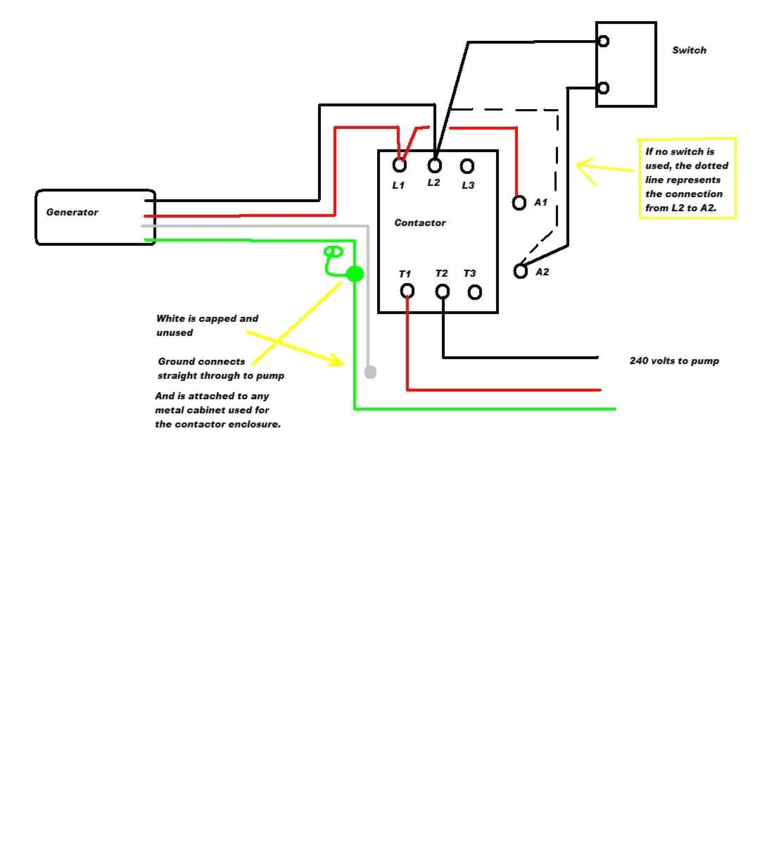
2 Pole Contactor Wiring Diagram
A set of wiring diagrams may be required by the electrical inspection authority to assume attachment of the domicile to the public electrical supply system.
Wiring diagrams will as well as enhance panel schedules for circuit breaker panelboards, and riser diagrams for special services such as flame alarm or closed circuit television or new special services.
You Might Also Like :
double pole contactor wiring diagram another graphic:

3 Pole Double Throw Contactor
2 Pole Contactor 120v Coil Wiring Diagram – Wires & Decors
Single Pole Contactor Wiring Diagram


