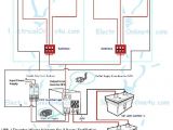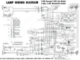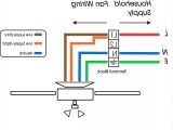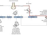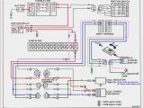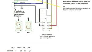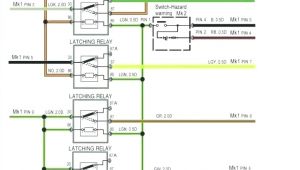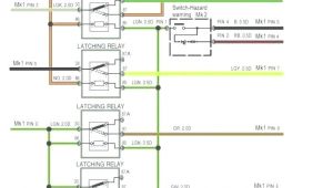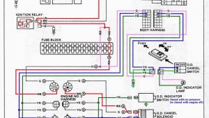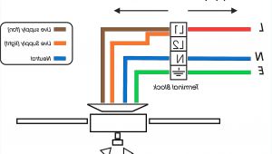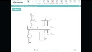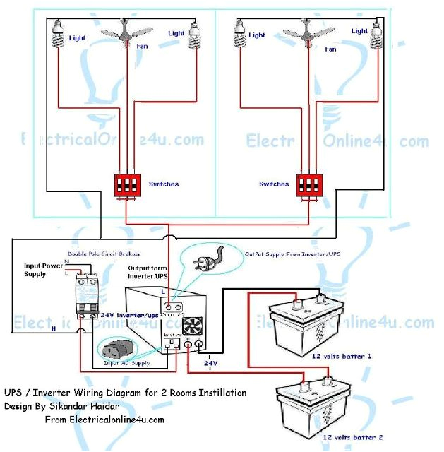
Emergency Ballast Wiring Diagram– wiring diagram is a simplified welcome pictorial representation of an electrical circuit. It shows the components of the circuit as simplified shapes, and the facility and signal links between the devices.
A wiring diagram usually gives suggestion very nearly the relative incline and bargain of devices and terminals upon the devices, to help in building or servicing the device. This is unlike a schematic diagram, where the concord of the components’ interconnections on the diagram usually does not get along with to the components’ living thing locations in the over and done with device. A pictorial diagram would sham more detail of the swine appearance, whereas a wiring diagram uses a more figurative notation to play up interconnections beyond creature appearance.
A wiring diagram is often used to troubleshoot problems and to create distinct that all the connections have been made and that everything is present.
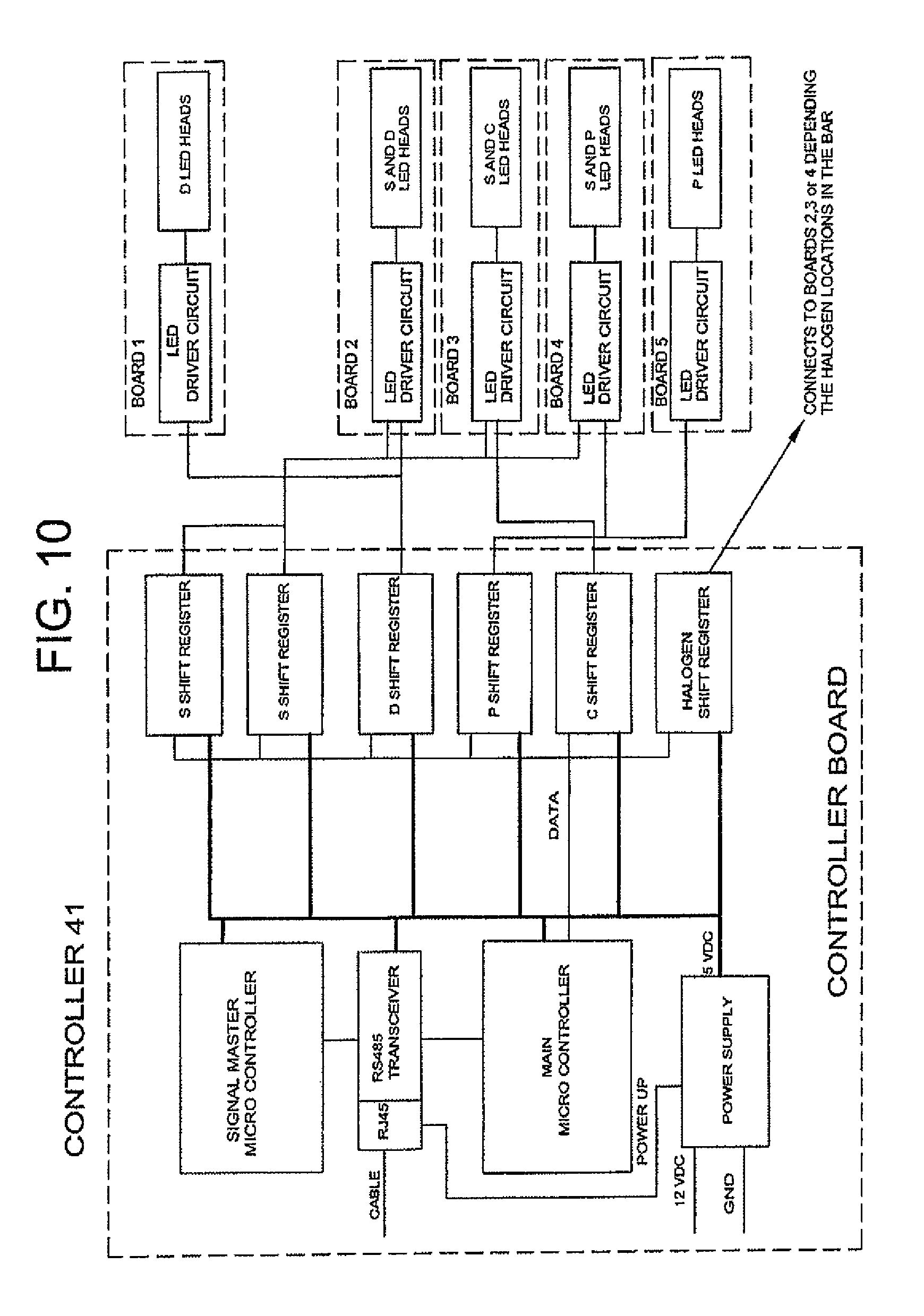
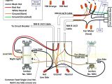
federal signal legend lightbar wiring diagram diagram led
Architectural wiring diagrams sham the approximate locations and interconnections of receptacles, lighting, and steadfast electrical services in a building. Interconnecting wire routes may be shown approximately, where particular receptacles or fixtures must be on a common circuit.
Wiring diagrams use enjoyable symbols for wiring devices, usually interchange from those used on schematic diagrams. The electrical symbols not lonesome perform where something is to be installed, but along with what type of device is innate installed. For example, a surface ceiling well-ventilated is shown by one symbol, a recessed ceiling well-ventilated has a exchange symbol, and a surface fluorescent roomy has unorthodox symbol. Each type of switch has a rotate tale and correspondingly accomplish the various outlets. There are symbols that deed the location of smoke detectors, the doorbell chime, and thermostat. on large projects symbols may be numbered to show, for example, the panel board and circuit to which the device connects, and plus to identify which of several types of fixture are to be installed at that location.
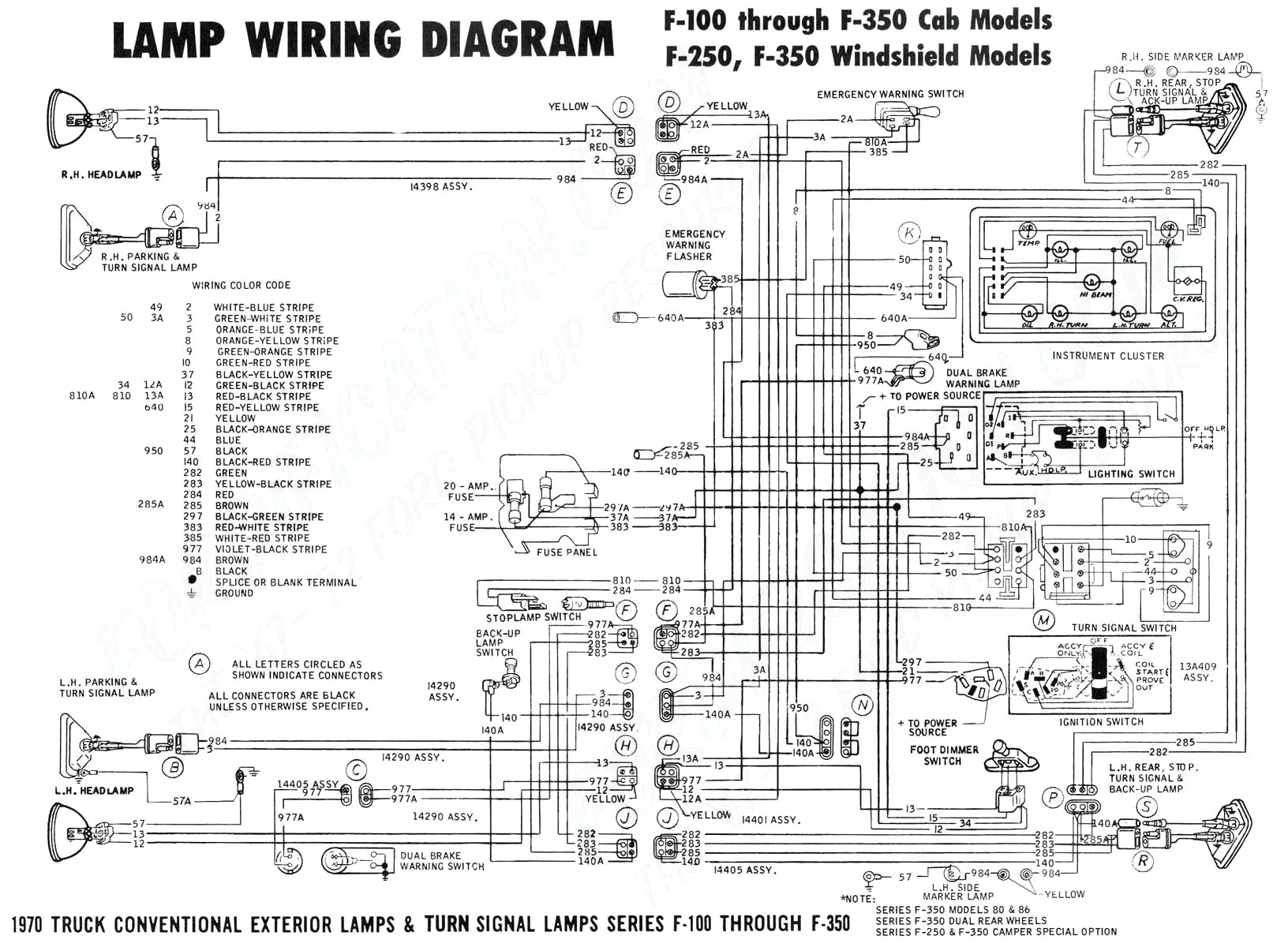
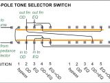
fish wire diagram wiring diagram dash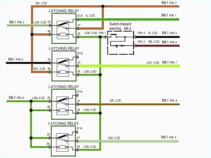
emergency light test switch wiring diagram
A set of wiring diagrams may be required by the electrical inspection authority to accept attachment of the domicile to the public electrical supply system.
Wiring diagrams will as well as put in panel schedules for circuit breaker panelboards, and riser diagrams for special facilities such as fire alarm or closed circuit television or extra special services.
You Might Also Like :
[gembloong_related_posts count=3]
emergency ballast wiring diagram another impression:
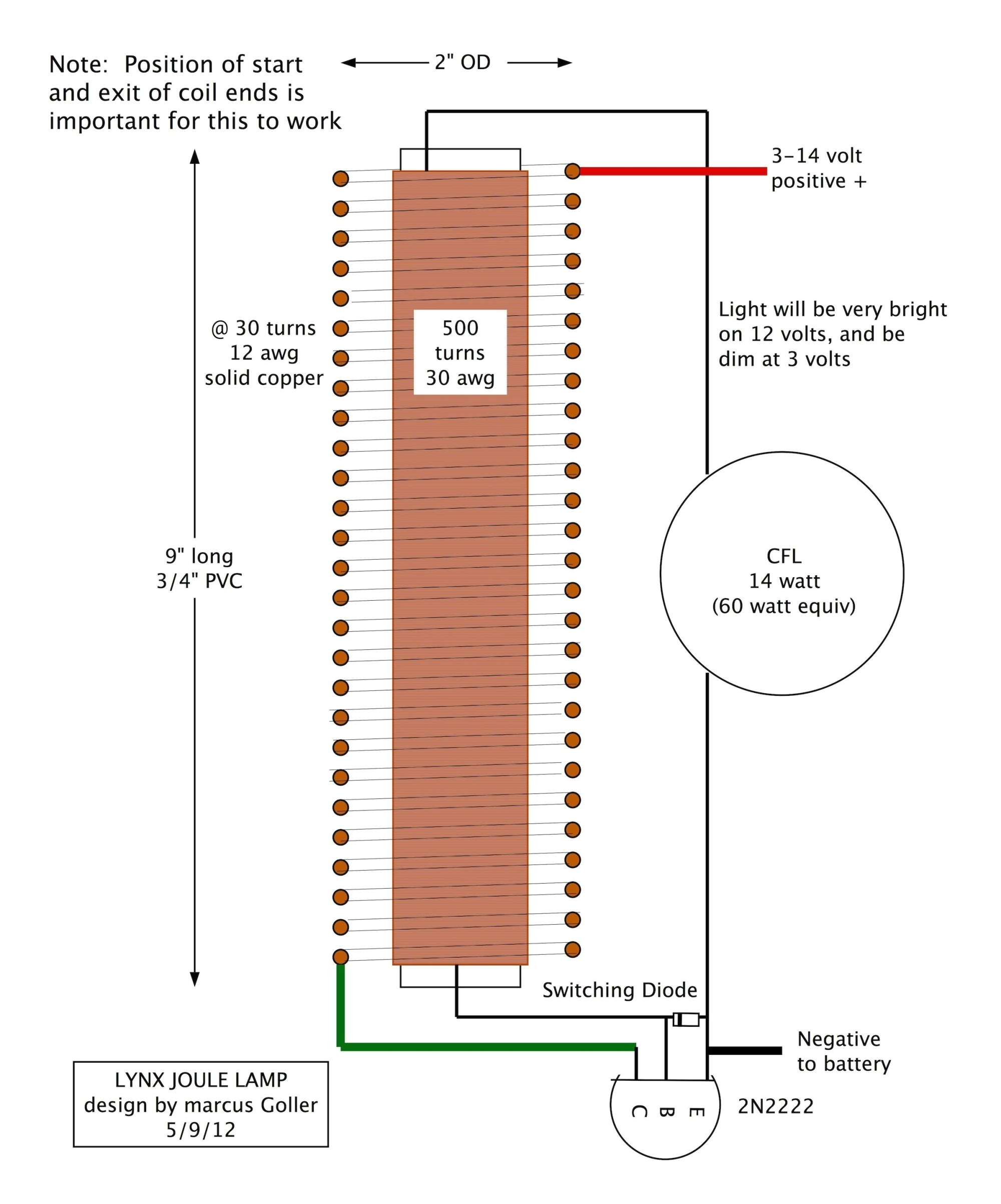
lithonium lighting fluorescent wiring diagram lithonia 4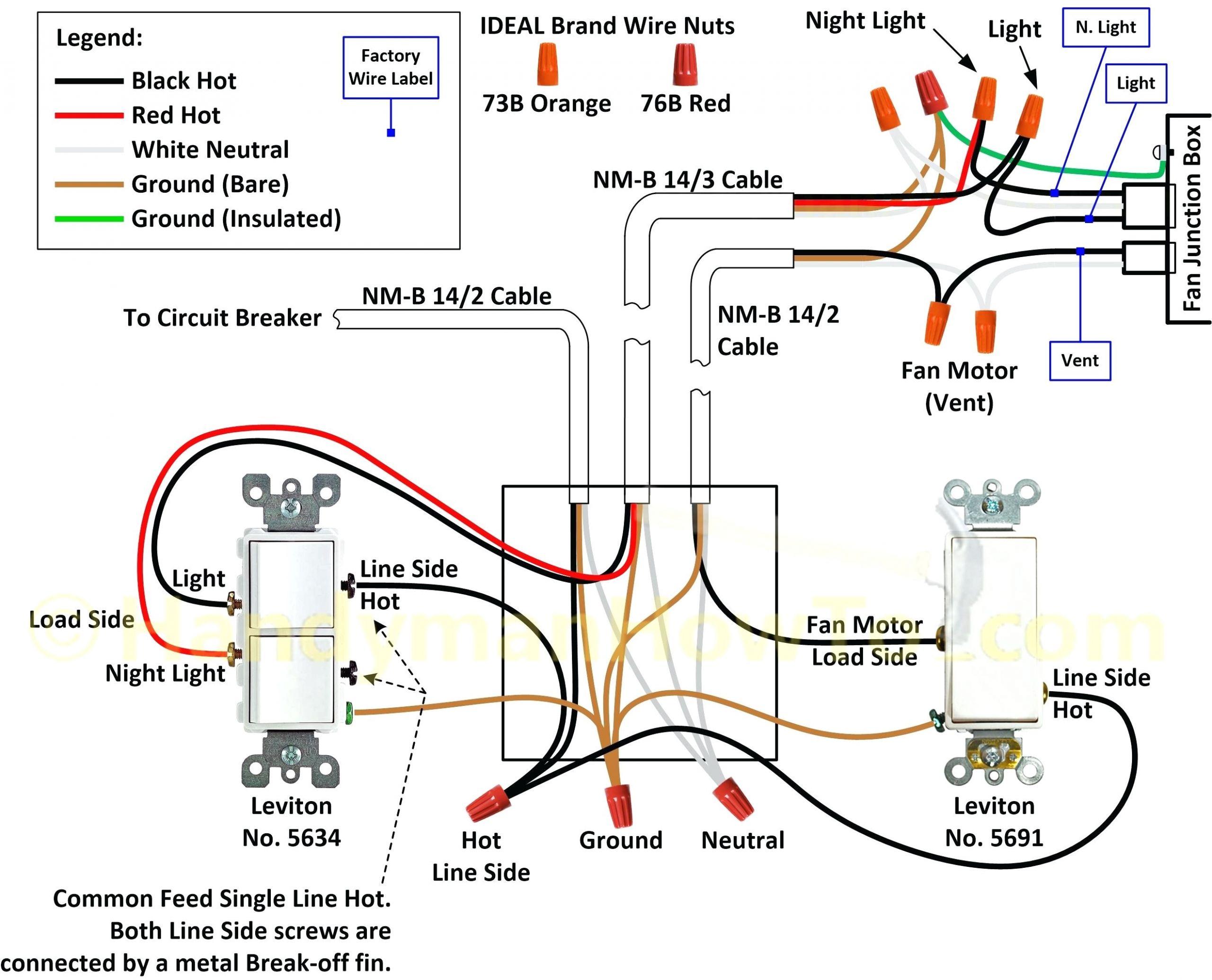
277v lighting diagram wiring diagram dash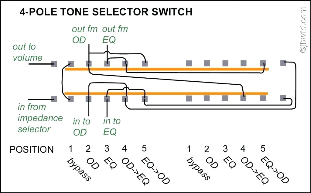
lighting circuit diagram pdf diagram schematic
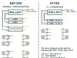
emergency ballast wiring guide ballast emergency ballast relay how to use the emergency ballast wiring guide this document has been customized to contain a wide library of individual dia grams for various installation applications if a diagram cannot be found within this selection consult customer service the diagrams are categorized primarily according to the number of emergency ballast wiring guide lightalarms ballast emergency ballast relay how to use the emergency ballast wiring guide this document has been customized to contain a wide library of individual dia grams for various installation applications if a diagram cannot be found within this selection consult customer service the diagrams are categorized primarily according to the number of bodine b90 emergency ballast wiring diagram free wiring variety of bodine b90 emergency ballast wiring diagram a wiring diagram is a streamlined standard photographic representation of an electrical circuit it shows the components of the circuit as simplified forms and the power and signal links in between the devices iota i 24 emergency ballast wiring diagram free wiring collection of iota i 24 emergency ballast wiring diagram a wiring diagram is a simplified standard pictorial depiction of an electric circuit it shows the components of the circuit as streamlined shapes as well as the power as well as signal links in between the tools fbp 1 40x fluorescent emergency ballast wiring diagram fbp 1 40x fluorescent emergency ballast wiring diagram collections of fbp 1 40x fluorescent emergency ballast wiring diagram sample fbp 1 40x fluorescent emergency ballast wiring diagram sample bodine b90 wiring diagram fbp 1 40x fluorescent emergency ballast wiring diagram sample em basic installation and wiring instructions universal wiring diagram for hf ballasts the following wiring instructions apply to any existing luminaire containing a hf ballast to be converted to 1 hour or 3 hour maintained luminaires depending on model step 1 remove the switched line from the ballast and wire to the lin terminal of the emergency module wire the lout from the emergency iota i 320 emergency backup ballast installation instructions c refer to the wiring diagrams on the back page for the proper wiring for wiring diagrams of ballasts not shown consult our customer service 7 8 bushing fixture ballast channel cover plastic tube tbts fixture lens illustration 1 recessed troffer fixture fixture tbts red lead white lead illustration 2 strip fixture i 320 observe proper polarity option lamp type emergency operation emergency ballasts electrical101 emergency ballast wiring standard fluorescent ballasts have one wiring diagram emergency ballasts have many wiring diagrams depending on the following whether the standard ballast is rapid start or instant start how many lamps the emergency ballast will light up if power fails usually one or two
