Engine Coolant Temperature Sensor Wiring Diagram– wiring diagram is a simplified normal pictorial representation of an electrical circuit. It shows the components of the circuit as simplified shapes, and the capability and signal contacts surrounded by the devices.
A wiring diagram usually gives guidance practically the relative position and concurrence of devices and terminals on the devices, to assist in building or servicing the device. This is unlike a schematic diagram, where the accord of the components’ interconnections upon the diagram usually does not settle to the components’ innate locations in the over and done with device. A pictorial diagram would proceed more detail of the swine appearance, whereas a wiring diagram uses a more figurative notation to put the accent on interconnections higher than being appearance.
A wiring diagram is often used to troubleshoot problems and to create sure that all the contacts have been made and that everything is present.

engine coolant temperature sensor wiring diagram awesome basic
Architectural wiring diagrams perform the approximate locations and interconnections of receptacles, lighting, and remaining electrical services in a building. Interconnecting wire routes may be shown approximately, where particular receptacles or fixtures must be on a common circuit.
Wiring diagrams use tolerable symbols for wiring devices, usually swing from those used upon schematic diagrams. The electrical symbols not lonesome statute where something is to be installed, but along with what type of device is visceral installed. For example, a surface ceiling light is shown by one symbol, a recessed ceiling vivacious has a every other symbol, and a surface fluorescent open has unusual symbol. Each type of switch has a oscillate tale and in view of that complete the various outlets. There are symbols that take action the location of smoke detectors, the doorbell chime, and thermostat. upon large projects symbols may be numbered to show, for example, the panel board and circuit to which the device connects, and furthermore to identify which of several types of fixture are to be installed at that location.

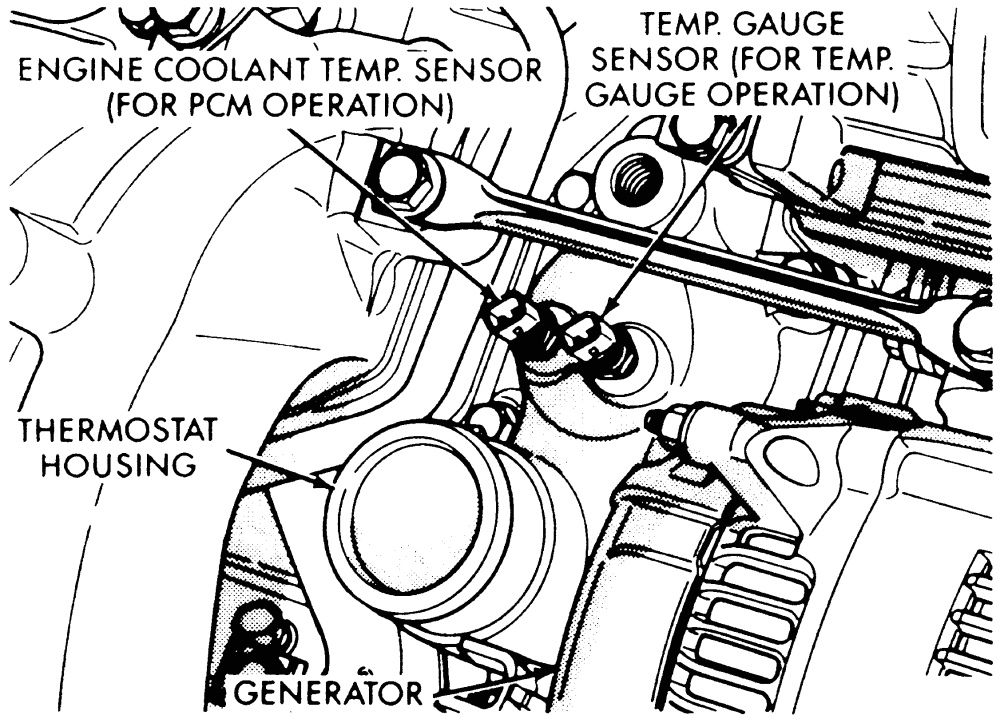
repair guides electronic engine controls engine coolant
72 toyota corolla wiring diagram wiring diagram database
A set of wiring diagrams may be required by the electrical inspection authority to espouse connection of the domicile to the public electrical supply system.
Wiring diagrams will furthermore count panel schedules for circuit breaker panelboards, and riser diagrams for special facilities such as fire alarm or closed circuit television or further special services.
You Might Also Like :
- 3 Phase House Wiring Diagram Pdf
- Vw Bug Ignition Coil Wiring Diagram
- Polaris Sportsman 500 Wiring Diagram Pdf
engine coolant temperature sensor wiring diagram another graphic:

coolant temp sensors 3vze yotatech forums
how to test your cherokee coolant sensor and wiring
repair guides electronic engine controls engine coolant


