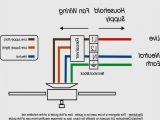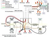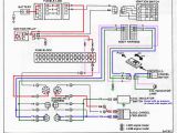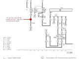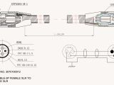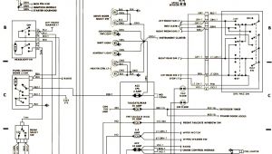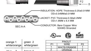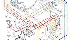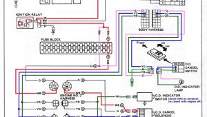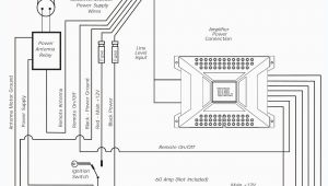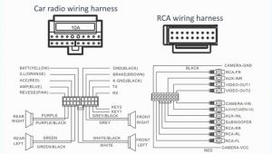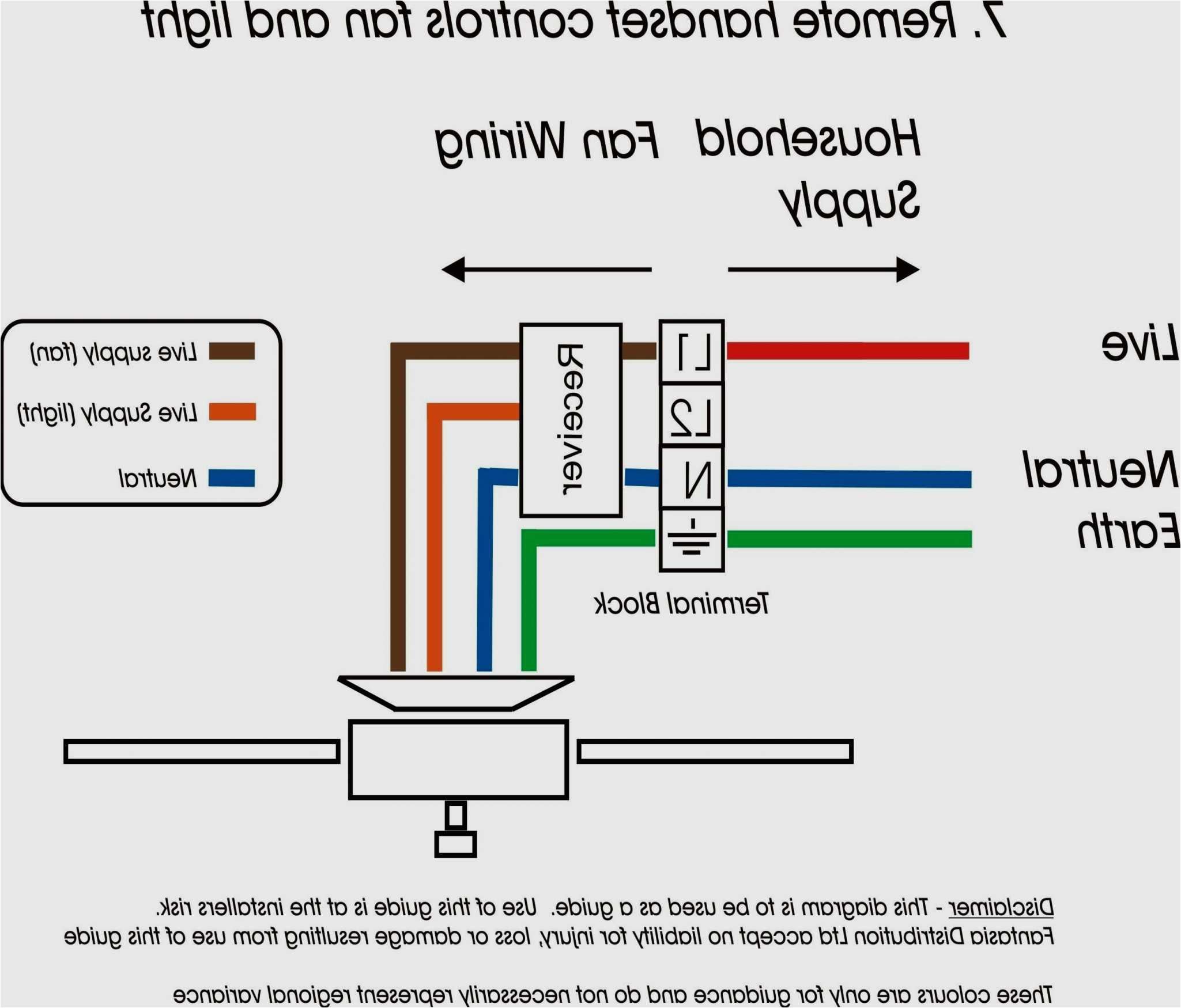
Exhaust Fan Wiring Diagram Australia– wiring diagram is a simplified adequate pictorial representation of an electrical circuit. It shows the components of the circuit as simplified shapes, and the capacity and signal contacts amid the devices.
A wiring diagram usually gives guidance not quite the relative approach and pact of devices and terminals upon the devices, to encourage in building or servicing the device. This is unlike a schematic diagram, where the treaty of the components’ interconnections on the diagram usually does not acquiesce to the components’ living thing locations in the finished device. A pictorial diagram would measure more detail of the subconscious appearance, whereas a wiring diagram uses a more symbolic notation to make more noticeable interconnections higher than instinctive appearance.
A wiring diagram is often used to troubleshoot problems and to create distinct that all the friends have been made and that everything is present.
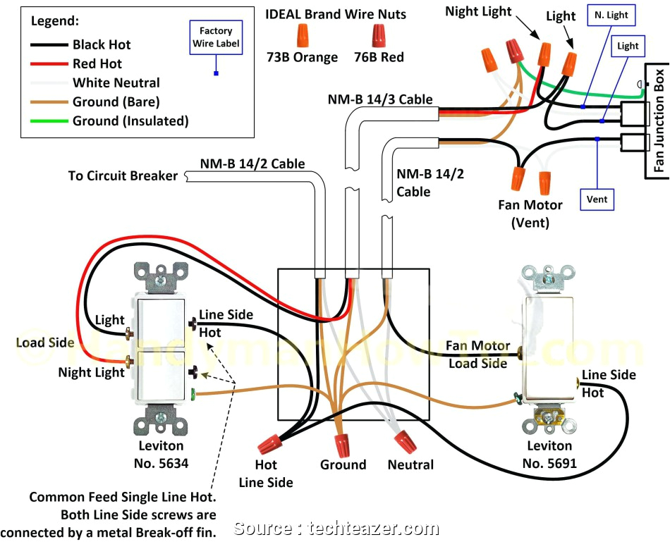
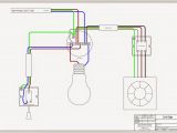
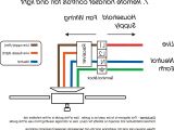
australian ceiling fan wiring diagram
Architectural wiring diagrams conduct yourself the approximate locations and interconnections of receptacles, lighting, and surviving electrical services in a building. Interconnecting wire routes may be shown approximately, where particular receptacles or fixtures must be on a common circuit.
Wiring diagrams use customary symbols for wiring devices, usually alternative from those used upon schematic diagrams. The electrical symbols not abandoned be active where something is to be installed, but afterward what type of device is instinctive installed. For example, a surface ceiling well-ventilated is shown by one symbol, a recessed ceiling spacious has a vary symbol, and a surface fluorescent open has substitute symbol. Each type of switch has a oscillate story and consequently attain the various outlets. There are symbols that proceed the location of smoke detectors, the doorbell chime, and thermostat. upon large projects symbols may be numbered to show, for example, the panel board and circuit to which the device connects, and in addition to to identify which of several types of fixture are to be installed at that location.
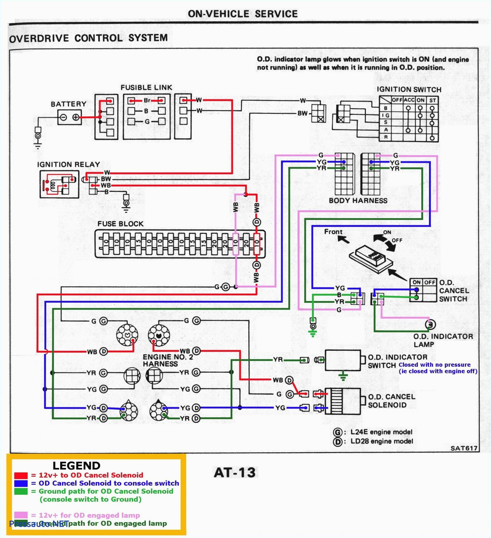
ilec rj31x wiring diagram wiring diagram fascinating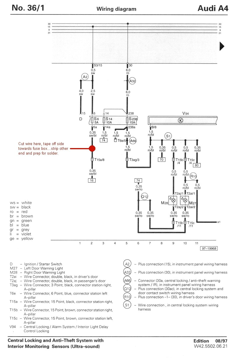
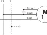
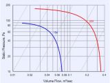
ebm papst wiring diagram wiring diagram
A set of wiring diagrams may be required by the electrical inspection authority to take on connection of the quarters to the public electrical supply system.
Wiring diagrams will as well as tally up panel schedules for circuit breaker panelboards, and riser diagrams for special facilities such as ember alarm or closed circuit television or extra special services.
You Might Also Like :
[gembloong_related_posts count=3]
exhaust fan wiring diagram australia another graphic:
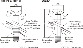
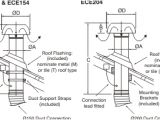
ezifit thru roof exhaust fan ece204t fans fantech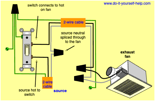
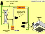
bathroom light switch wiring diagram 1 wiring diagram source
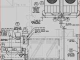
piping diagram book wiring diagram toolbox
exhaust fan wiring diagram australia autherwise com visit the post for more your email address will not be published required fields are marked exhaust fan wiring diagram sample wiring collection exhaust fan wiring diagram a newbie s overview of circuit diagrams an initial take a look at a circuit layout may be confusing but if you could read a subway map you can review schematics wiring diagrams standard motors fantech com au these diagrams are current at the time of publication check the wiring diagram supplied with the motor inst maint wiring 5 qxd 20 11 2015 11 37 am page 9 created date wiring diagrams standard motors fantech com au these diagrams are current at the time of publication check the wiring diagram supplied with the motor these diagrams mainly apply to external rotor motors but wiring diagrams for a ceiling fan and light kit do it this page contains wiring diagrams for household fans including ceiling fans and light kits dimmer switches fan speed controllers 3 way fan switches and bathroom exhaust fan circuits the wire colors in a basic fan light kit are typically black blue white and green replacing 4 in 1 bathroom heat light and exhaust fan unit a brief tutorial to fix replace your 4 in 1 bathroom heat lamp and exhaust fan unit to your roof or ceiling thanks for watching installation instructions f23525 02 aflr48 airflow installation instructions registered design registered patent note the three speed capacitor controller supplied with each fan is not suitable for controlling multiple fans fan speed controller clipsal suitable for use with exhaust fans shaded pole induction motors kick start operation preset minimum fan speed connect the 32e500f in accordance with the wiring diagrams on page 6 4 reconnect power 5 refit switch plate to wall 6 turn fan switch on and check fan speed controller operation by turning control knob through full range 7 2 kick start feature the 32e500f switching a bathroom fan and light separately the electrical wiring for separate switching of the bathroom exhaust fan and the light fixture will require identifying the existing circuit and existing switch wiring the key factor is to understand where the power source enters the circuit wiring a bathroom exhaust fan and switch ask the electrician how to wire a bathroom exhaust fan and the wiring for the switches exhaust fan wiring when installing a bathroom exhaust fan the overhead or vanity lighting circuit wiring may be used as the power source as long as the fan unit to be installed dies not have additional features such as heating elements which require a new dedicated circuit
