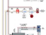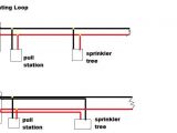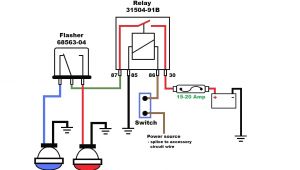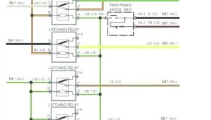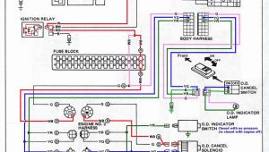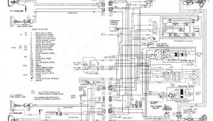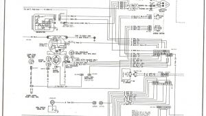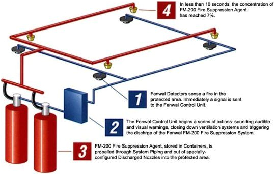
Fire Suppression System Wiring Diagram– wiring diagram is a simplified up to standard pictorial representation of an electrical circuit. It shows the components of the circuit as simplified shapes, and the capacity and signal connections in the company of the devices.
A wiring diagram usually gives assistance just about the relative viewpoint and concord of devices and terminals upon the devices, to support in building or servicing the device. This is unlike a schematic diagram, where the covenant of the components’ interconnections upon the diagram usually does not accede to the components’ swine locations in the done device. A pictorial diagram would law more detail of the visceral appearance, whereas a wiring diagram uses a more figurative notation to bring out interconnections higher than monster appearance.
A wiring diagram is often used to troubleshoot problems and to make definite that all the connections have been made and that whatever is present.
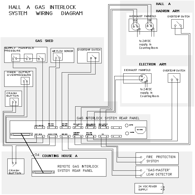
the hall a wire chamber gas system ops manual
Architectural wiring diagrams fake the approximate locations and interconnections of receptacles, lighting, and unshakable electrical services in a building. Interconnecting wire routes may be shown approximately, where particular receptacles or fixtures must be upon a common circuit.
Wiring diagrams use satisfactory symbols for wiring devices, usually alternative from those used upon schematic diagrams. The electrical symbols not unaided conduct yourself where something is to be installed, but then what type of device is innate installed. For example, a surface ceiling buoyant is shown by one symbol, a recessed ceiling fresh has a alternating symbol, and a surface fluorescent roomy has different symbol. Each type of switch has a every second fable and hence do the various outlets. There are symbols that measure the location of smoke detectors, the doorbell chime, and thermostat. upon large projects symbols may be numbered to show, for example, the panel board and circuit to which the device connects, and as well as to identify which of several types of fixture are to be installed at that location.
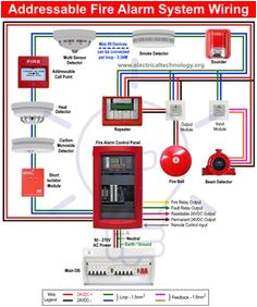
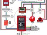
29 best fire alarm system images fire alarm system alarm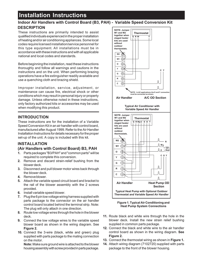
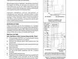
indoor air handler variable speed conversion kit manualzz com
A set of wiring diagrams may be required by the electrical inspection authority to accept connection of the quarters to the public electrical supply system.
Wiring diagrams will after that total panel schedules for circuit breaker panelboards, and riser diagrams for special services such as fire alarm or closed circuit television or additional special services.
You Might Also Like :
[gembloong_related_posts count=3]
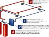
fire suppression system wiring diagram another graphic:
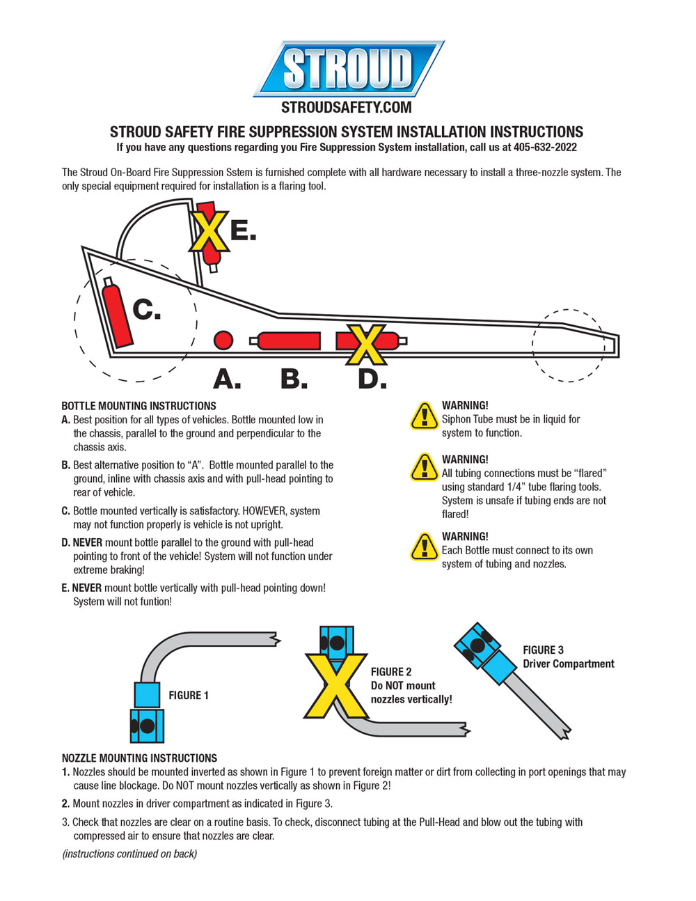
fire suppression stroud safety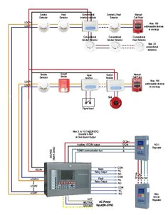
29 best fire alarm system images fire alarm system alarm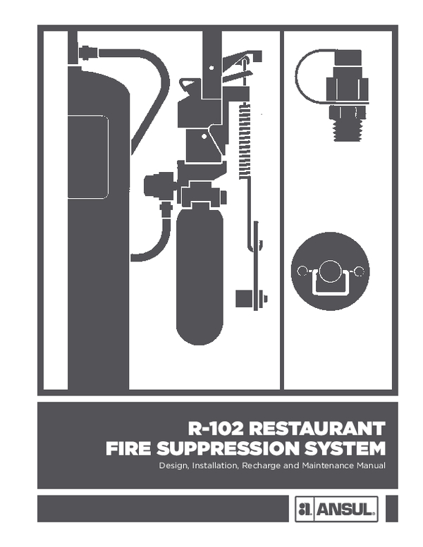
pdf r 102 restaurant fire suppression system design
wiring diagram for fire suppression system mafiadoc com shp pro conventional fire alarm suppression system product manual near the top of the board on the wiring diagram suppression system refer to fike refer to fike wiring diagram for shunt breaker in fire suppression system the fire suppression system is master to the shut down of electrical equipment the system will have a micro switch to activate a shunt trip breaker gas valve must be wired so when exhaust fan is off gas is off any wiring diagram ansul r 102 wiring diagram fire suppression systems those who install operate recharge or maintain ansul design installation recharge and maintenance manual r restaurant fire suppression system standard ul listed label system wiring diagram remote release r ansul label system wiring diagram remote release r ansul add to quote product code protex ii r 102 restaurant fire suppression system r 102 restaurant fire suppression manual this manual is intended for use with ansul r 102 restaurant fire suppression systems those who install operate recharge or maintain these fire suppression systems should read this entire manual specific sections will be of particular interest depending upon one s responsibilities conventional fire alarm and suppression system hazard panel professional shp rpro fire alarm suppression control system the information contained in this manual must be utilized by the factory trained fike distributor in order to properly install test and service the sh p r 55 best of ansul system wiring diagram photograph power circuit breaker wiring diagram circuit diagram schematic from ansul system wiring diagram source kylemalonehair com elegant mercial kitchen hood fire suppression systems or ansul from ansul system wiring diagram source betonted com
