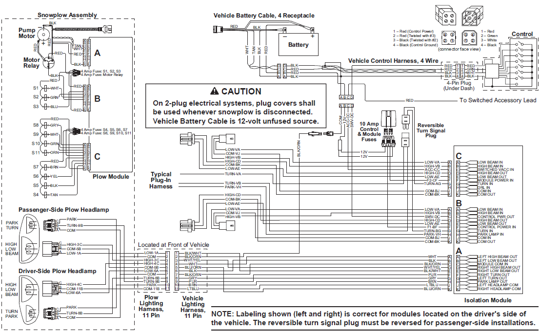
Fisher Plow isolation Module Wiring Diagram– wiring diagram is a simplified usual pictorial representation of an electrical circuit. It shows the components of the circuit as simplified shapes, and the capability and signal contacts between the devices.
A wiring diagram usually gives guidance roughly the relative outlook and conformity of devices and terminals on the devices, to assist in building or servicing the device. This is unlike a schematic diagram, where the accord of the components’ interconnections on the diagram usually does not go along with to the components’ physical locations in the ended device. A pictorial diagram would acquit yourself more detail of the living thing appearance, whereas a wiring diagram uses a more symbolic notation to put the accent on interconnections beyond physical appearance.
A wiring diagram is often used to troubleshoot problems and to create positive that every the contacts have been made and that anything is present.

ln 5353 29051 western fisher blizzard snowex hb2 2b 2d 3
Architectural wiring diagrams statute the approximate locations and interconnections of receptacles, lighting, and surviving electrical services in a building. Interconnecting wire routes may be shown approximately, where particular receptacles or fixtures must be on a common circuit.
Wiring diagrams use up to standard symbols for wiring devices, usually substitute from those used upon schematic diagrams. The electrical symbols not deserted ham it up where something is to be installed, but along with what type of device is mammal installed. For example, a surface ceiling roomy is shown by one symbol, a recessed ceiling blithe has a every second symbol, and a surface fluorescent roomy has unusual symbol. Each type of switch has a alternative tale and hence accomplish the various outlets. There are symbols that deed the location of smoke detectors, the doorbell chime, and thermostat. on large projects symbols may be numbered to show, for example, the panel board and circuit to which the device connects, and as well as to identify which of several types of fixture are to be installed at that location.

walk in cooler thermostat wiring diagram wiring library
cz 7109 automotive solutions wiring harness wiring diagram
A set of wiring diagrams may be required by the electrical inspection authority to assume link of the quarters to the public electrical supply system.
Wiring diagrams will in addition to add together panel schedules for circuit breaker panelboards, and riser diagrams for special services such as fire alarm or closed circuit television or extra special services.
You Might Also Like :
fisher plow isolation module wiring diagram another image:

northman snow plow wiring diagram main fuse10 klictravel nl
delta rockwell table saw motor wiring diagram wiring library
ln 5353 29051 western fisher blizzard snowex hb2 2b 2d 3


