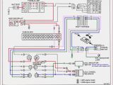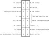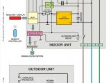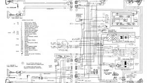
Ge Ecm 2.3 Motor Wiring Diagram– wiring diagram is a simplified customary pictorial representation of an electrical circuit. It shows the components of the circuit as simplified shapes, and the skill and signal associates amid the devices.
A wiring diagram usually gives instruction just about the relative perspective and concord of devices and terminals upon the devices, to back up in building or servicing the device. This is unlike a schematic diagram, where the promise of the components’ interconnections on the diagram usually does not concur to the components’ instinctive locations in the done device. A pictorial diagram would play more detail of the physical appearance, whereas a wiring diagram uses a more symbolic notation to bring out interconnections on top of subconscious appearance.
A wiring diagram is often used to troubleshoot problems and to make certain that every the contacts have been made and that whatever is present.
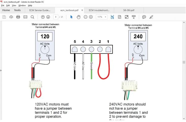
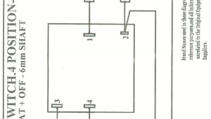
ecm x13 motor wiring diagram wiring diagram
Architectural wiring diagrams do its stuff the approximate locations and interconnections of receptacles, lighting, and long-lasting electrical services in a building. Interconnecting wire routes may be shown approximately, where particular receptacles or fixtures must be upon a common circuit.
Wiring diagrams use standard symbols for wiring devices, usually interchange from those used on schematic diagrams. The electrical symbols not by yourself ham it up where something is to be installed, but plus what type of device is innate installed. For example, a surface ceiling blithe is shown by one symbol, a recessed ceiling spacious has a substitute symbol, and a surface fluorescent blithe has unconventional symbol. Each type of switch has a exchange tale and therefore realize the various outlets. There are symbols that be active the location of smoke detectors, the doorbell chime, and thermostat. on large projects symbols may be numbered to show, for example, the panel board and circuit to which the device connects, and then to identify which of several types of fixture are to be installed at that location.
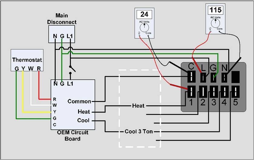
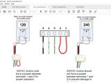
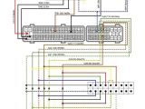
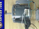
ecm x13 motor wiring diagram wiring diagram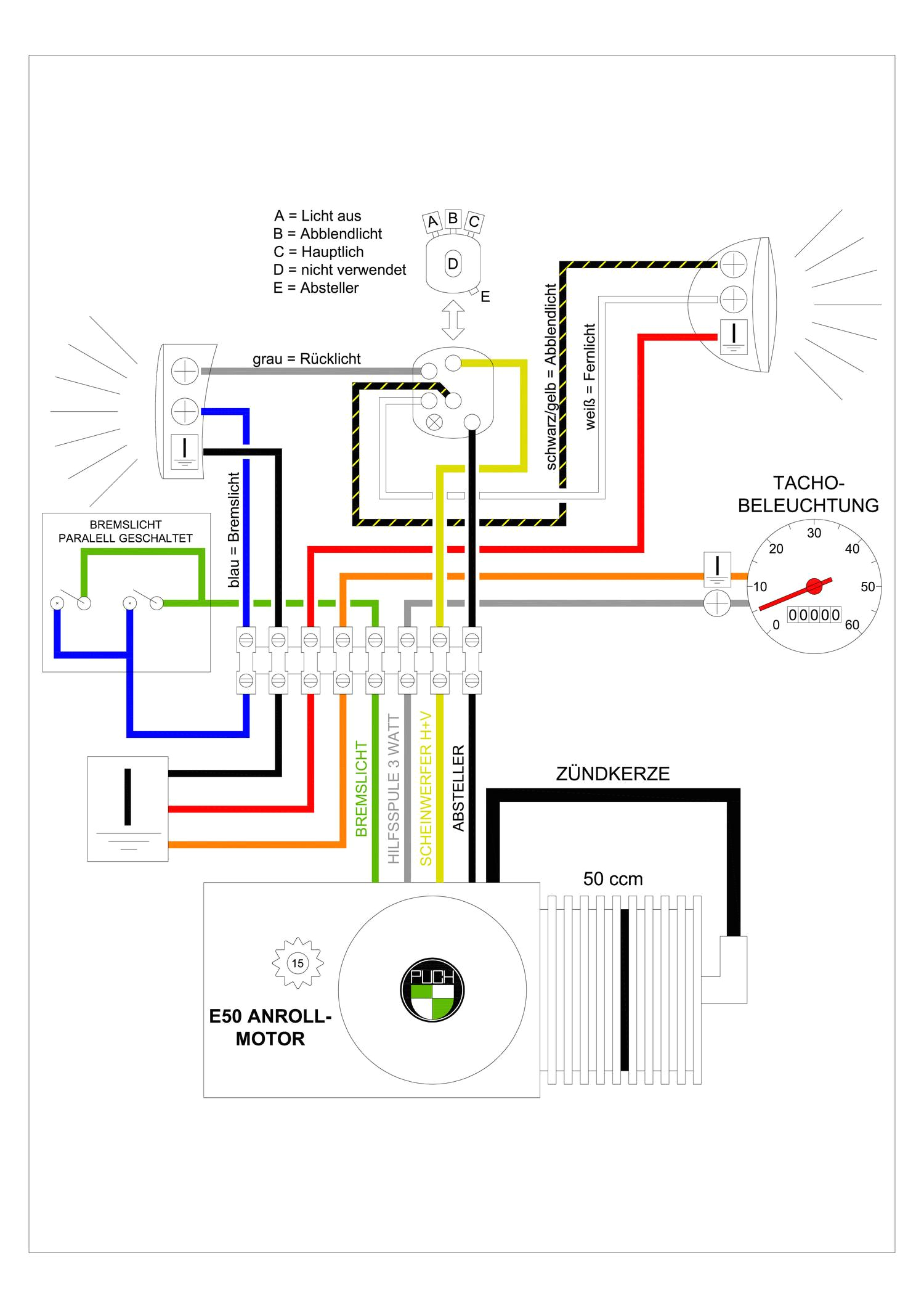
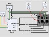
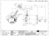
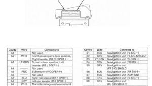
ecm x13 motor wiring diagram wiring diagram
A set of wiring diagrams may be required by the electrical inspection authority to agree to membership of the dwelling to the public electrical supply system.
Wiring diagrams will along with tote up panel schedules for circuit breaker panelboards, and riser diagrams for special facilities such as flame alarm or closed circuit television or other special services.
You Might Also Like :
[gembloong_related_posts count=3]
ge ecm 2.3 motor wiring diagram another impression:
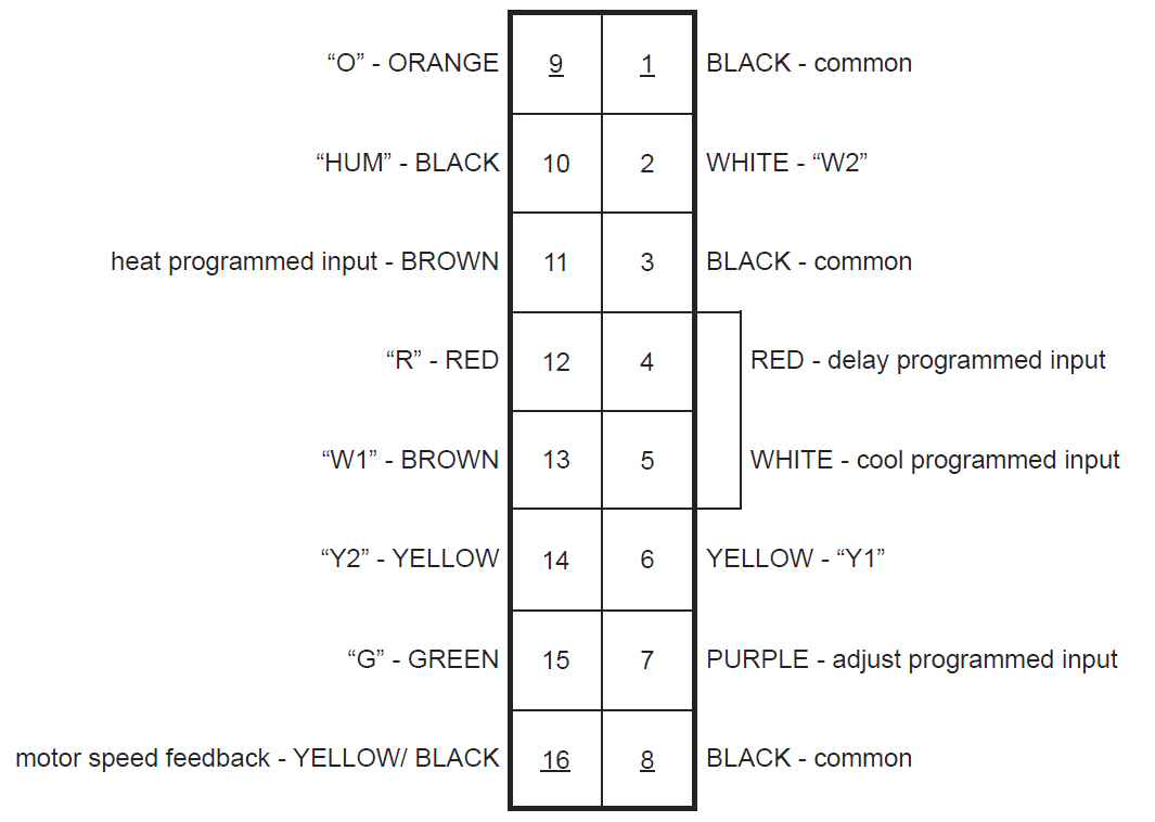
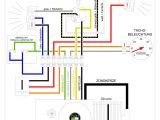
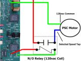
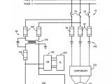
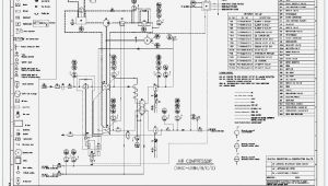
ecm x13 motor wiring diagram wiring diagram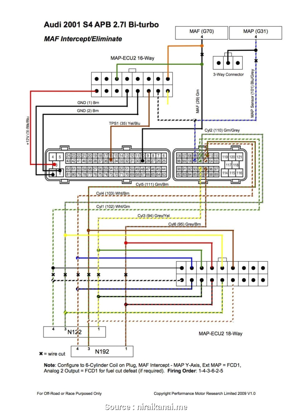
ecm x13 motor wiring diagram wiring diagram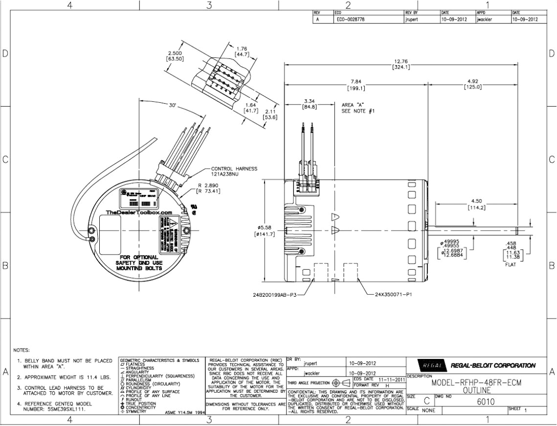
ecm x13 motor wiring diagram wiring diagram
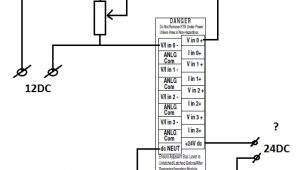
ge ecm 2 3 motor wiring diagram wiring diagram resource free ge ecm 2 3 motor wiring diagram disclaimer we never admit that the image is our image the copyright is in the image owner we only help our users to find the information they are looking for quickly if you want the image to be deleted please contact us we will delete it from our website ge ecm 2 3 motor wiring diagram wirings diagram ecm motor wiring diagram carrier ecm motor wiring diagram ecm 2 3 motor wiring diagram ecm blower motor wiring diagram every electrical arrangement is composed of various unique components each component should be set and linked to different parts in specific manner otherwise the structure schematic diagram for ge ecm 2 3 motor module air conditioning and cooling systems schematic diagram for ge ecm 2 3 motor module have 2 trane ac systems one is not working got a contractor and found motor and motor control module need be ge 2 3 ecm controller below options are unused wiring diagrams signal common rpm neutral neutral 24 vac 24 vac on off rpm gnd pwm motor connector 120 vac 24 tran vac icm711 g t c signal common rpm neutral neutral 24 vac 24 vac on off rpm gnd motor connector 120 vac 24 tran vac icm711 g t c v v constant power power supplied by automated controller gnd on off pwm rpm replaces evo ecm ge ecm motor wiring diagram free diagram for student ge ecm 2 3 motor wiring diagram trusted wiring diagrams ge ecm x13 motor wiring diagram for 8 arcnx co rh arcnx co genteq wiring diagrams 5kcp39bgr201bs ecm blower motor wiring diagram commutated motor ecm by automated control systems via a 0 10v input signal common or manually via potentiometer set ge ecm 2 3 motor wiring diagram wiring diagram ge ecm 2 3 motor wiring diagram 2002 toyota tundra wiring diagram hvac wiring diagram test 2000 ford mustang stereo wiring diagram vw beetle wiper wiring diagram free download collection ford trailer plug wiring diagram pictures wire home entertainment wiring residential home wiring 1999 pontiac engine diagram 68 camaro parking light wiring ecm 2 3 variable speed blower motor hvac how to ecm 2 3 motors are used in hvac systems frequently these days as blower motors this includes air conditioners heat pumps and furnaces it can adjust the air flow depending on what the system is getting for feedback ecm 2 3 schematic hvac talk heating air does anyone know have schematics for an ge ecm 2 3 motor weblinks pdf s etc i ve got a dead one and i m willing to take it apart and mess with it who knows also if anyone has the schematic for the control board wires located on air handler mainboard like the ones on carrier bryant air handler that will be very apreciated
