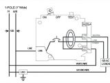
Ground Fault Breaker Wiring Diagram– wiring diagram is a simplified adequate pictorial representation of an electrical circuit. It shows the components of the circuit as simplified shapes, and the faculty and signal connections in the midst of the devices.
A wiring diagram usually gives suggestion about the relative approach and treaty of devices and terminals on the devices, to assist in building or servicing the device. This is unlike a schematic diagram, where the concord of the components’ interconnections upon the diagram usually does not allow to the components’ physical locations in the finished device. A pictorial diagram would proceed more detail of the living thing appearance, whereas a wiring diagram uses a more figurative notation to make more noticeable interconnections beyond monster appearance.
A wiring diagram is often used to troubleshoot problems and to make positive that every the associates have been made and that all is present.
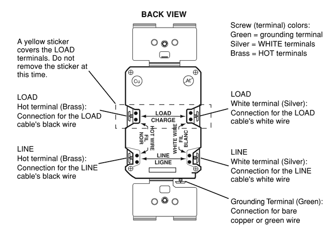
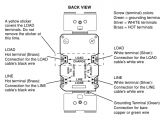
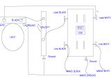
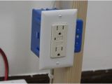
wiring a gfci outlet how to wire line and load schematics
Architectural wiring diagrams play-act the approximate locations and interconnections of receptacles, lighting, and unshakable electrical services in a building. Interconnecting wire routes may be shown approximately, where particular receptacles or fixtures must be upon a common circuit.
Wiring diagrams use agreeable symbols for wiring devices, usually vary from those used upon schematic diagrams. The electrical symbols not only proceed where something is to be installed, but furthermore what type of device is bodily installed. For example, a surface ceiling open is shown by one symbol, a recessed ceiling buoyant has a swing symbol, and a surface fluorescent roomy has complementary symbol. Each type of switch has a every other story and appropriately attain the various outlets. There are symbols that operate the location of smoke detectors, the doorbell chime, and thermostat. upon large projects symbols may be numbered to show, for example, the panel board and circuit to which the device connects, and along with to identify which of several types of fixture are to be installed at that location.
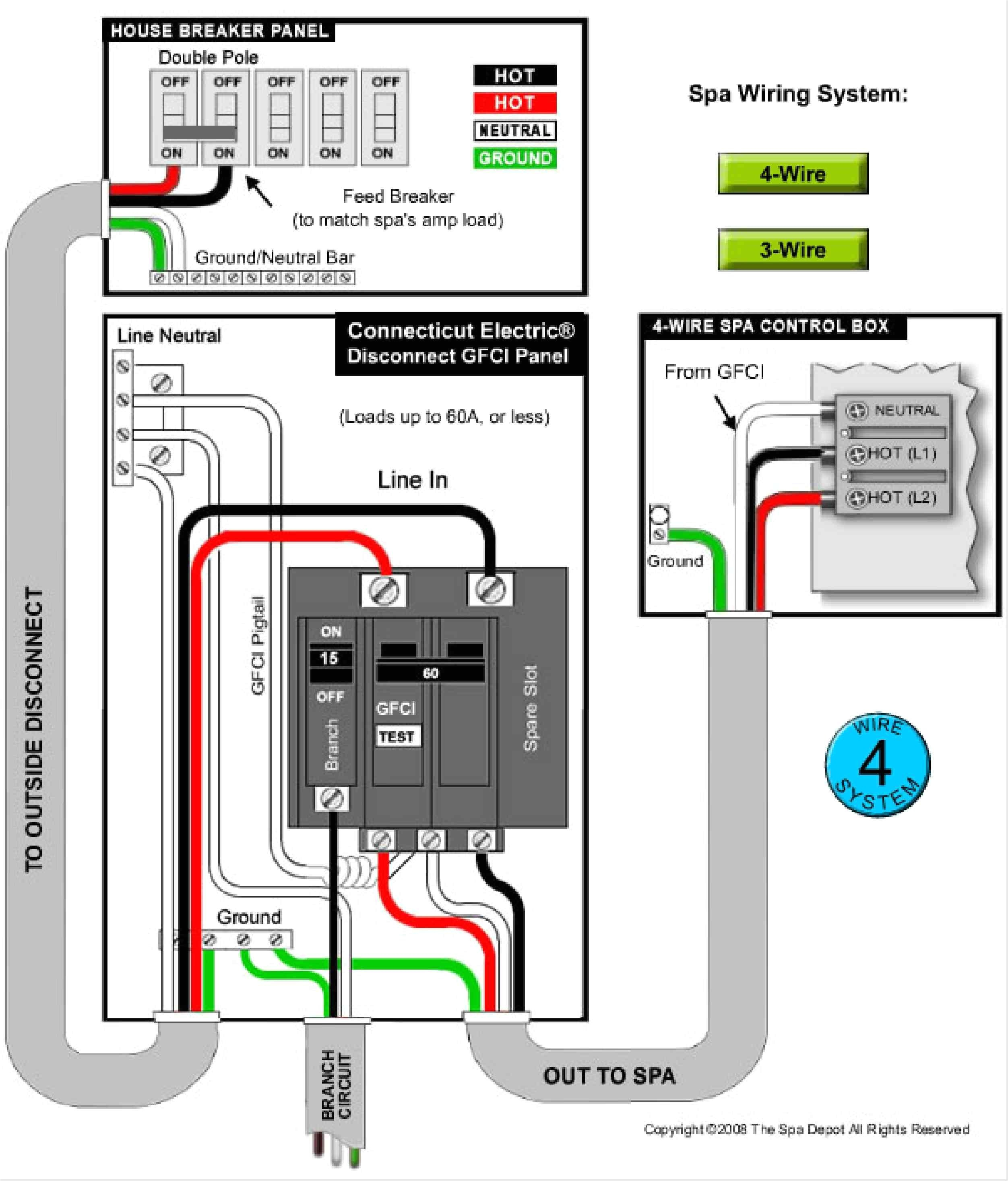
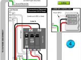
wiring diagram for circuit breaker get free image about wiring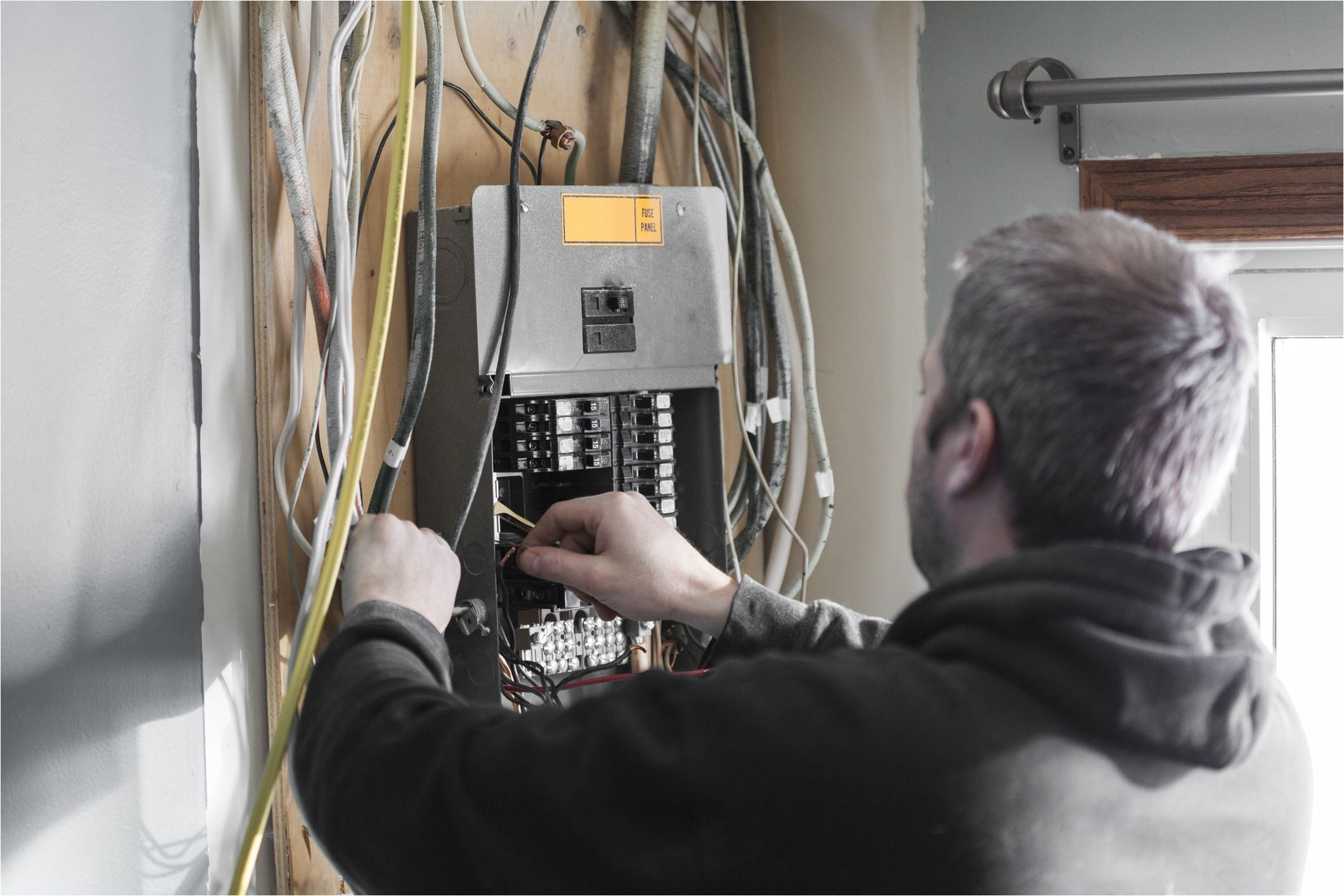
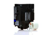
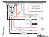
how to install a ground fault breaker
A set of wiring diagrams may be required by the electrical inspection authority to take up attachment of the dwelling to the public electrical supply system.
Wiring diagrams will as well as count up panel schedules for circuit breaker panelboards, and riser diagrams for special facilities such as fire alarm or closed circuit television or new special services.
You Might Also Like :
[gembloong_related_posts count=3]
ground fault breaker wiring diagram another impression:
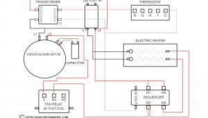
on off heater control circuit diagram tradeoficcom wiring diagram etc
240v gfci outlet woodworking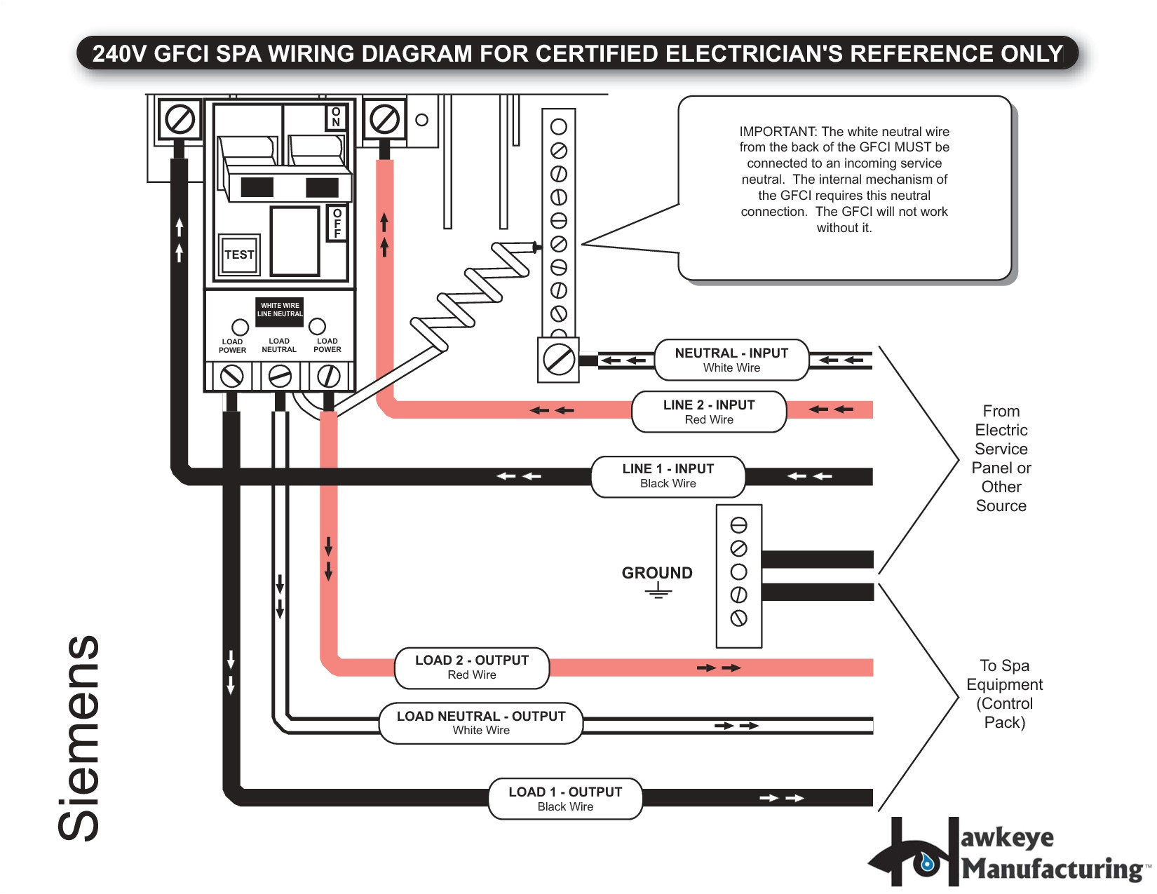
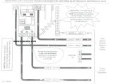
3 pole schematic wiring wiring diagram var
how to install a ground fault breaker the spruce a ground fault circuit breaker is properly called a ground fault circuit interrupter breaker or simply a gfci breaker it installs into a home s service panel or breaker box and provides gfci protection for the entire branch circuit it serves ground fault breaker wiring diagram wiring diagram chart ground fault breaker wiring diagram amazing arc fault breaker wiring diagram frieze best images for ground fault breaker wiring diagram wiring diagram gfci fresh gfci wiring diagram without ground valid wiring diagrams for gfci outlets do it yourself help com this page contains wiring diagrams for ground fault circuit interrupter gfci receptacles included are diagrams for multiple gfci s a protected standard duplex receptacle and a protected light fixture wiring for a switch and gfci receptacle in the same box is also shown installing a gfi or afi breaker schneider electric support tutorial for installing and wiring a ground or arc fault breaker into a panel qo or homeline load center panel this device must only be installed or serviced by qualified personnel after all how to wire a gfci circuit breaker hunker the ground fault circuit interrupter gfci saves lives there are two different kinds for home use electrical outlets and circuit breakers gfci circuit breakers last longer than gfci outlets and are a good idea if you do not test your gfci outlets on a regular basis wiring a 220 volt gfci breaker wiring diagram and schematics wiring a 220 volt gfci breaker jul 14 2019 this best picture collections about wiring a 220 volt gfci breaker is available to save we collect this best photo from internet and choose one of the best for you gfci circuit breaker and wiring ask the electrician gfci ground fault circuit breakers gfci wiring gfci wiring this list of articles will help you learn about the features and benefits provided by gfi and gfci receptacles and how they are wired gfci code requirements electrical panel circuit listing for more information about circuit breaker circuit breaker circuit breaker a guide to home electrical circuit breakers and how they work to wiring a gfci outlet how to wire line and load schematics refer to the attached gfci outlet wiring diagram above for clarity or contact our in office electrician in mesa az free of charge line side connections the line terminals of a gfci outlet connect to the power supply conductors that are connect at the circuit breaker or fuse box circuit breaker wiring diagrams do it yourself help com this wiring diagram illustrates installing a 15 amp circuit breaker for a 120 volt branch circuit the 14 2 awg cable for this circuit includes 2 conductors and 1 ground wire a 15 amp circuit is usually used for wall receptacle outlets and room light fixtures
