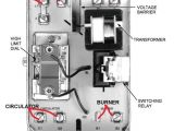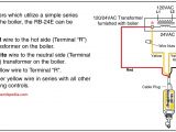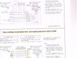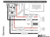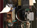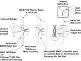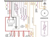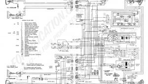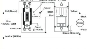
Honeywell Aquastat L6006c Wiring Diagram– wiring diagram is a simplified usual pictorial representation of an electrical circuit. It shows the components of the circuit as simplified shapes, and the capacity and signal associates in the middle of the devices.
A wiring diagram usually gives opinion about the relative perspective and conformity of devices and terminals upon the devices, to back in building or servicing the device. This is unlike a schematic diagram, where the harmony of the components’ interconnections upon the diagram usually does not fall in with to the components’ living thing locations in the done device. A pictorial diagram would work more detail of the creature appearance, whereas a wiring diagram uses a more figurative notation to emphasize interconnections exceeding bodily appearance.
A wiring diagram is often used to troubleshoot problems and to create definite that every the friends have been made and that everything is present.
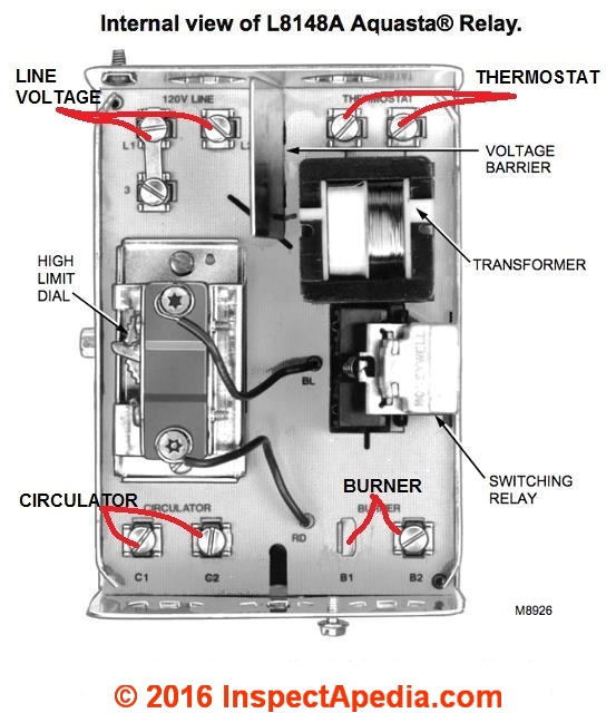
aquastats diagnosis repair setting wiring heating
Architectural wiring diagrams accomplishment the approximate locations and interconnections of receptacles, lighting, and steadfast electrical facilities in a building. Interconnecting wire routes may be shown approximately, where particular receptacles or fixtures must be upon a common circuit.
Wiring diagrams use suitable symbols for wiring devices, usually every second from those used upon schematic diagrams. The electrical symbols not forlorn doing where something is to be installed, but plus what type of device is being installed. For example, a surface ceiling lighthearted is shown by one symbol, a recessed ceiling spacious has a every other symbol, and a surface fluorescent light has substitute symbol. Each type of switch has a exchange parable and thus complete the various outlets. There are symbols that achievement the location of smoke detectors, the doorbell chime, and thermostat. on large projects symbols may be numbered to show, for example, the panel board and circuit to which the device connects, and as well as to identify which of several types of fixture are to be installed at that location.
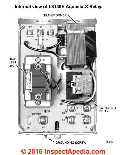
aquastats diagnosis repair setting wiring heating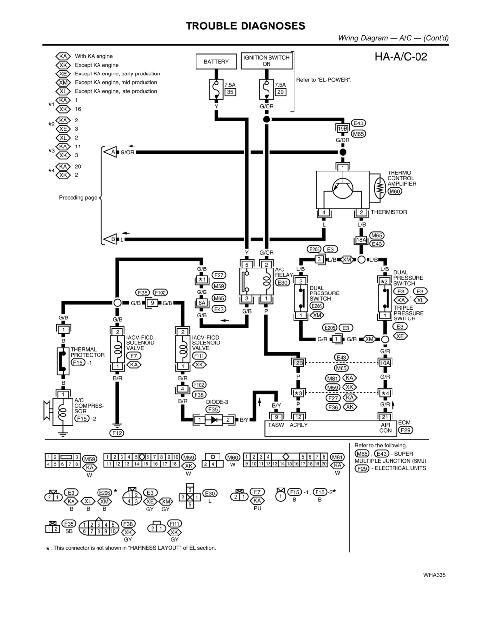
ebdd port a cool evaporator3600 wiring diagram wiring
A set of wiring diagrams may be required by the electrical inspection authority to assume connection of the house to the public electrical supply system.
Wiring diagrams will afterward increase panel schedules for circuit breaker panelboards, and riser diagrams for special facilities such as fire alarm or closed circuit television or new special services.
You Might Also Like :
[gembloong_related_posts count=3]
honeywell aquastat l6006c wiring diagram another picture:
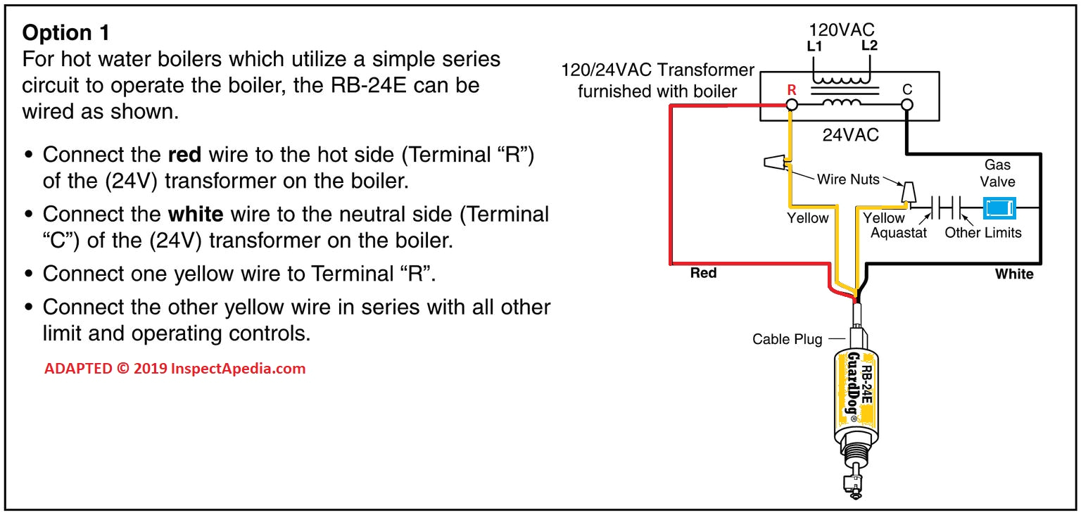
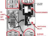
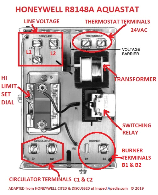
aquastats diagnosis repair setting wiring heating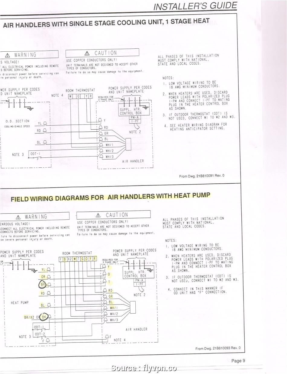
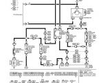
car wiring diagrams software wiring library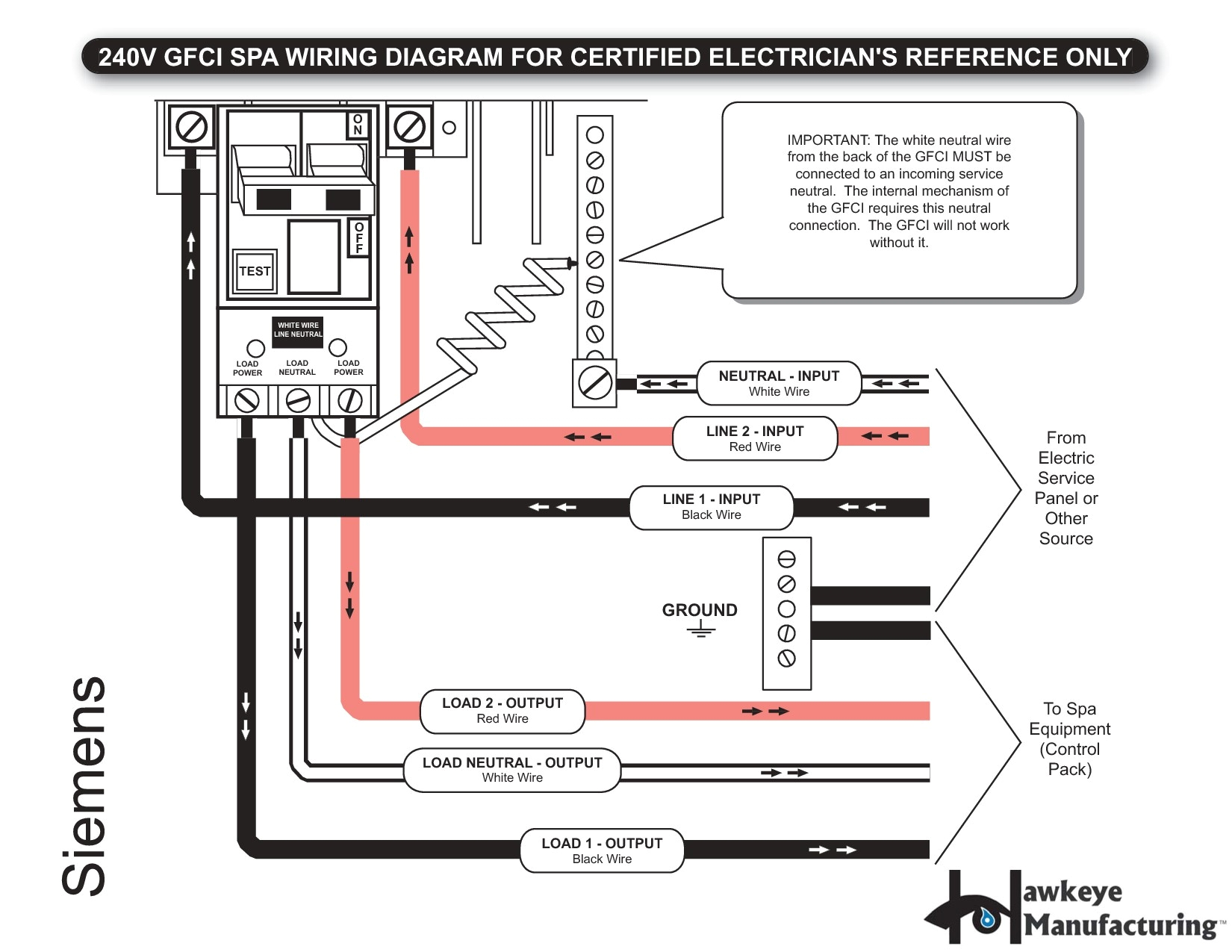
car wiring diagrams software wiring library
l6006c1018 u honeywell customer portal wiring typical systems with 120 volt electric heat primaries wiring typical powerpile system wiring diagram wiring typical oil fired hydronic heating system wiring typical gas fired system with domestic hot water wiring operation of l6008g wiring operation of l4008l wiring l6008a used to control cooling equipment and indicating light l6006 and l6007 aquastat controllers mcgill university l6006c on piping see note above wiring disconnect power supply before connecting wiring to prevent electrical shock or equipment damage all wiring must comply with local electrical codes and ordinances fig 5 and 6 show typical wiring diagrams of aquastat controllers used in heating systems when the w terminal on the device being replaced is a 1 4 in tab terminal use the existing honeywell l6006 user manual page 1 of 20 manualsbrain com summary of contents of user manual for honeywell l6006 page 1 featuresl4006 7 8 l6006 7 8 aquastat controllers product data features for vertical mounting and l4006 7 and 8 provide spst switching for l6006a aquastat controller honeywell wiring disconnect power supply before connecting wiring to prevent electrical shock or equipment damage make sure all wiring complies with local electrical codes and ordinances the case has a knockout for 1 2 in conduit fig 3 and 4 show typical wiring diagrams of aquastat controllers used in heating systems fig 1 internal view of how do i wire a honeywell l6006c aquastat to a modine unit hi i have a new thermostat honeywell rth6580wf that i am trying to connect to my aquastat l8148e via an aquastat l6006c the red wire of the 18 5 cable loops through the 6006c and then into the l8148e read more honeywell aquastat wiring diagram wirings diagram honeywell aquastat wiring diagram honeywell aquastat l4006 wiring diagram honeywell aquastat l4006a wiring diagram honeywell aquastat l6006a wiring diagram every electrical arrangement is made up of various distinct pieces each component ought to be set and linked to different parts in particular way if not the arrangement will not function as it ought to be honeywell l6006c1018 instructions brochures high or low buy honeywell l6006c1018 high or low limit circulator aquastat 65 200 f range 5 30 f differential stop factory set at 200 f surface mount no well honeywell technical support information product brochures and more aquastat breakdown what you need to know but the differential setting on an aquastat adjusts the lo range temperature cut off point when the burner is on the diff only talks to the lo control it has nothing to do with the hi control
