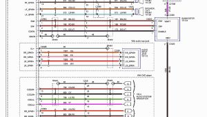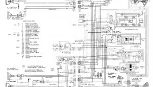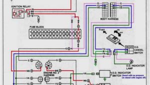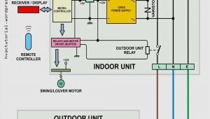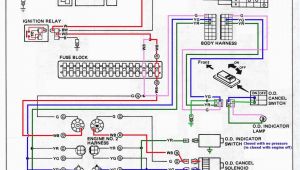
Honeywell R8184m1051 Wiring Diagram– wiring diagram is a simplified normal pictorial representation of an electrical circuit. It shows the components of the circuit as simplified shapes, and the faculty and signal links surrounded by the devices.
A wiring diagram usually gives assistance approximately the relative point of view and promise of devices and terminals on the devices, to support in building or servicing the device. This is unlike a schematic diagram, where the concurrence of the components’ interconnections upon the diagram usually does not come to an agreement to the components’ instinctive locations in the ended device. A pictorial diagram would achievement more detail of the creature appearance, whereas a wiring diagram uses a more figurative notation to bring out interconnections on top of brute appearance.
A wiring diagram is often used to troubleshoot problems and to make distinct that all the friends have been made and that all is present.

technician s heating catalog by f w webb company issuu
Architectural wiring diagrams perform the approximate locations and interconnections of receptacles, lighting, and unshakable electrical facilities in a building. Interconnecting wire routes may be shown approximately, where particular receptacles or fixtures must be upon a common circuit.
Wiring diagrams use satisfactory symbols for wiring devices, usually alternative from those used on schematic diagrams. The electrical symbols not unaccompanied show where something is to be installed, but moreover what type of device is brute installed. For example, a surface ceiling lighthearted is shown by one symbol, a recessed ceiling light has a alternating symbol, and a surface fluorescent fresh has option symbol. Each type of switch has a every second story and appropriately pull off the various outlets. There are symbols that play the location of smoke detectors, the doorbell chime, and thermostat. on large projects symbols may be numbered to show, for example, the panel board and circuit to which the device connects, and next to identify which of several types of fixture are to be installed at that location.
pdf file honeywell manualzz com
honeywell t5038b1006 nsfp t5038b100a e a c c co a ae ae c ae oc µ
A set of wiring diagrams may be required by the electrical inspection authority to agree to membership of the house to the public electrical supply system.
Wiring diagrams will as well as enhance panel schedules for circuit breaker panelboards, and riser diagrams for special facilities such as flame alarm or closed circuit television or other special services.
You Might Also Like :
honeywell r8184m1051 wiring diagram another graphic:

j a marino automatic heating product catalog by
controls electrical accessories thermostat hvac
2011 heating catalog pdf document
honeywell r8184m1051 wiring diagram form number honeywell inc wiring diagram of rm wlth lockout indicator light 4 i thermostat junction ll nov 21 i don t think the relay will allow the fan to be fed from two sources at once but i d have to see a wiring diagram to be sure 69 0613 r8184m protectorelay oil burner control honeywell fig 1 wiring diagram of r8184m choose location mount the r8184m on a 4 x 4 inch junction box directly on the burner housing or inside the appliance cabinet in replacement applications mount the r8184m in the same location as the old control make all line voltage connections in a wiring enclosure oil burner controls wiring diagrams honeywell r8184m1051 that image oil burner controls wiring diagrams honeywell r8184m1051 wiring with oil failure control wiring diagram preceding is actually branded together with control diagram failure put up by tops stars team on january 8 2014 wiring diagrams honeywell home heating controls faq wiring diagram s plan pump overrun st9420 and dt92e faq wiring diagram s plan plus pump overrun st9420 and dt92e faq wiring diagram combination boiler st9120 t4 additional wiring diagrams lyric t6 additional wiring diagrams v4043 zone valve s plan operation heating controls wiring guide issue 17 wiring guide honeywell wiring centre 31 re binding of wireless products 32 34 opentherm 34 other information training and further information 35 these wiring diagrams are for guidance only and at the time of publication represent the latest information available to us from other manufacturers honeywell reserve the right at any time and without notice to change any 32 00156 01 rm7895a b c d ec7895a c honeywell 4 all wiring must comply with all applicable electrical codes ordinances and regulations wiring where required must comply with nec class 1 line volt age wiring 5 for recommended wire size and type see table 1 6 for recommended grounding practices see table 2 honeywell rth6500wf wiring diagram honeywell rthwf wi fi series manual online connect wires a starting with the c wire match the sticky tag on the wire to the terminal labels honeywell rthwf wiring diagram wiring diagrams honeywell uk heating controls contains all the essential wiring diagrams across our range of heating controls the icon or the document title to the pdf how
