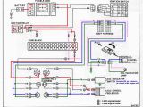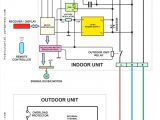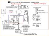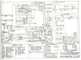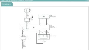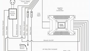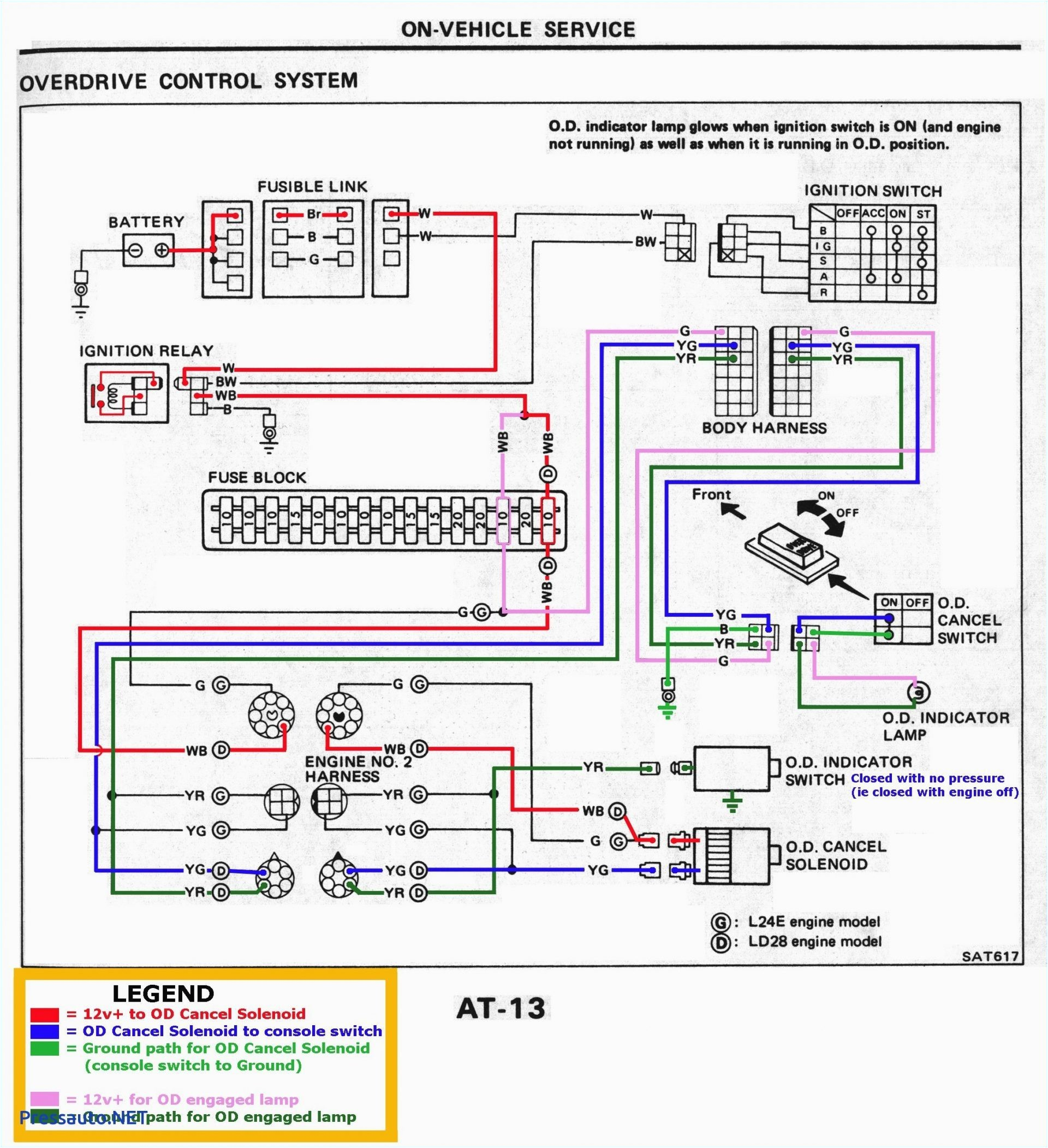
Honeywell R8239a1052 Wiring Diagram– wiring diagram is a simplified standard pictorial representation of an electrical circuit. It shows the components of the circuit as simplified shapes, and the aptitude and signal connections amid the devices.
A wiring diagram usually gives guidance practically the relative incline and settlement of devices and terminals upon the devices, to back in building or servicing the device. This is unlike a schematic diagram, where the conformity of the components’ interconnections upon the diagram usually does not concur to the components’ monster locations in the the end device. A pictorial diagram would con more detail of the inborn appearance, whereas a wiring diagram uses a more figurative notation to put the accent on interconnections greater than monster appearance.
A wiring diagram is often used to troubleshoot problems and to make positive that every the associates have been made and that anything is present.
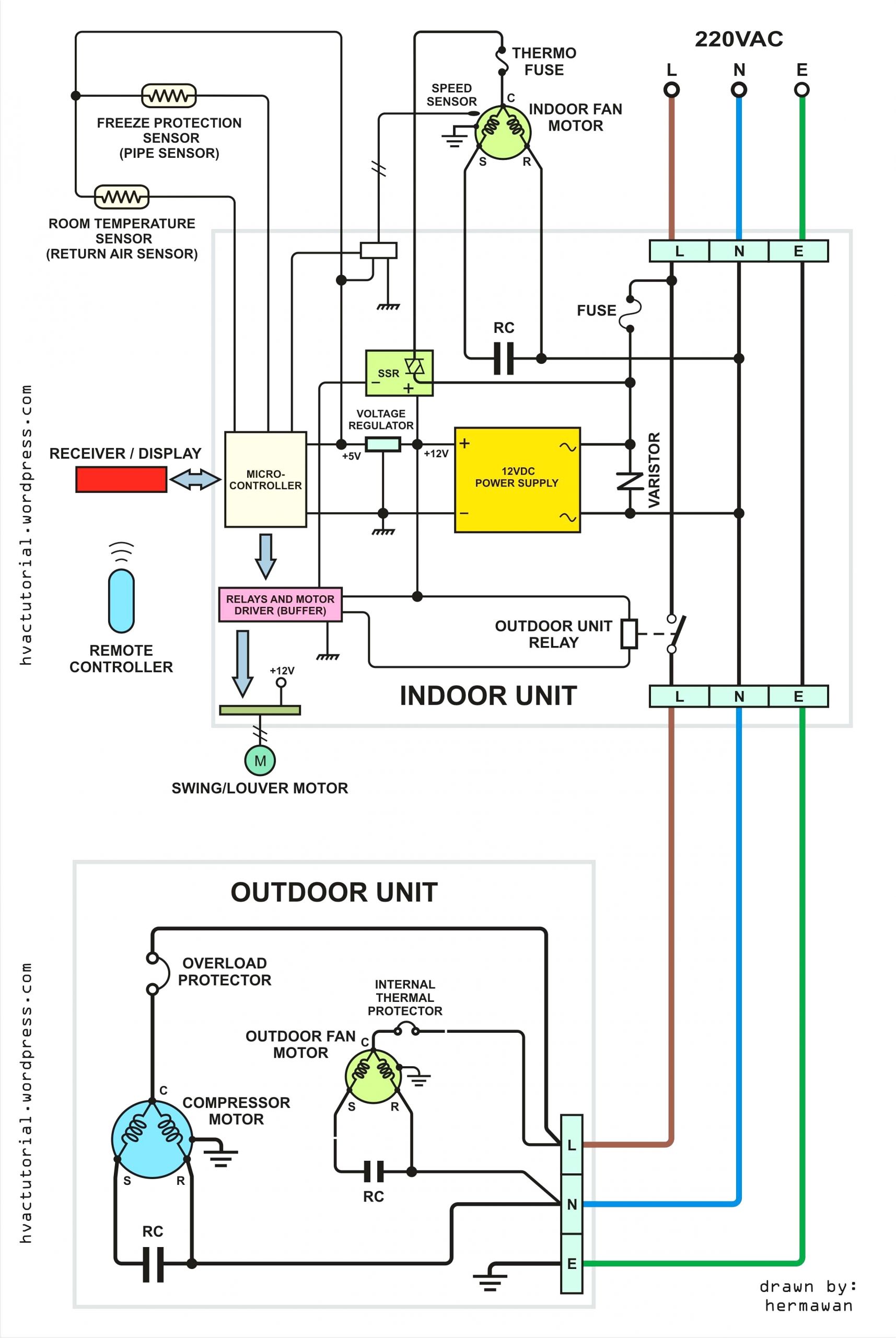
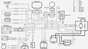
honeywell r8222b wiring diagram wiring schematic diagram
Architectural wiring diagrams affect the approximate locations and interconnections of receptacles, lighting, and surviving electrical services in a building. Interconnecting wire routes may be shown approximately, where particular receptacles or fixtures must be upon a common circuit.
Wiring diagrams use customary symbols for wiring devices, usually alternating from those used upon schematic diagrams. The electrical symbols not isolated action where something is to be installed, but also what type of device is visceral installed. For example, a surface ceiling lighthearted is shown by one symbol, a recessed ceiling buoyant has a every second symbol, and a surface fluorescent vivacious has option symbol. Each type of switch has a substitute story and for that reason attain the various outlets. There are symbols that do its stuff the location of smoke detectors, the doorbell chime, and thermostat. on large projects symbols may be numbered to show, for example, the panel board and circuit to which the device connects, and also to identify which of several types of fixture are to be installed at that location.
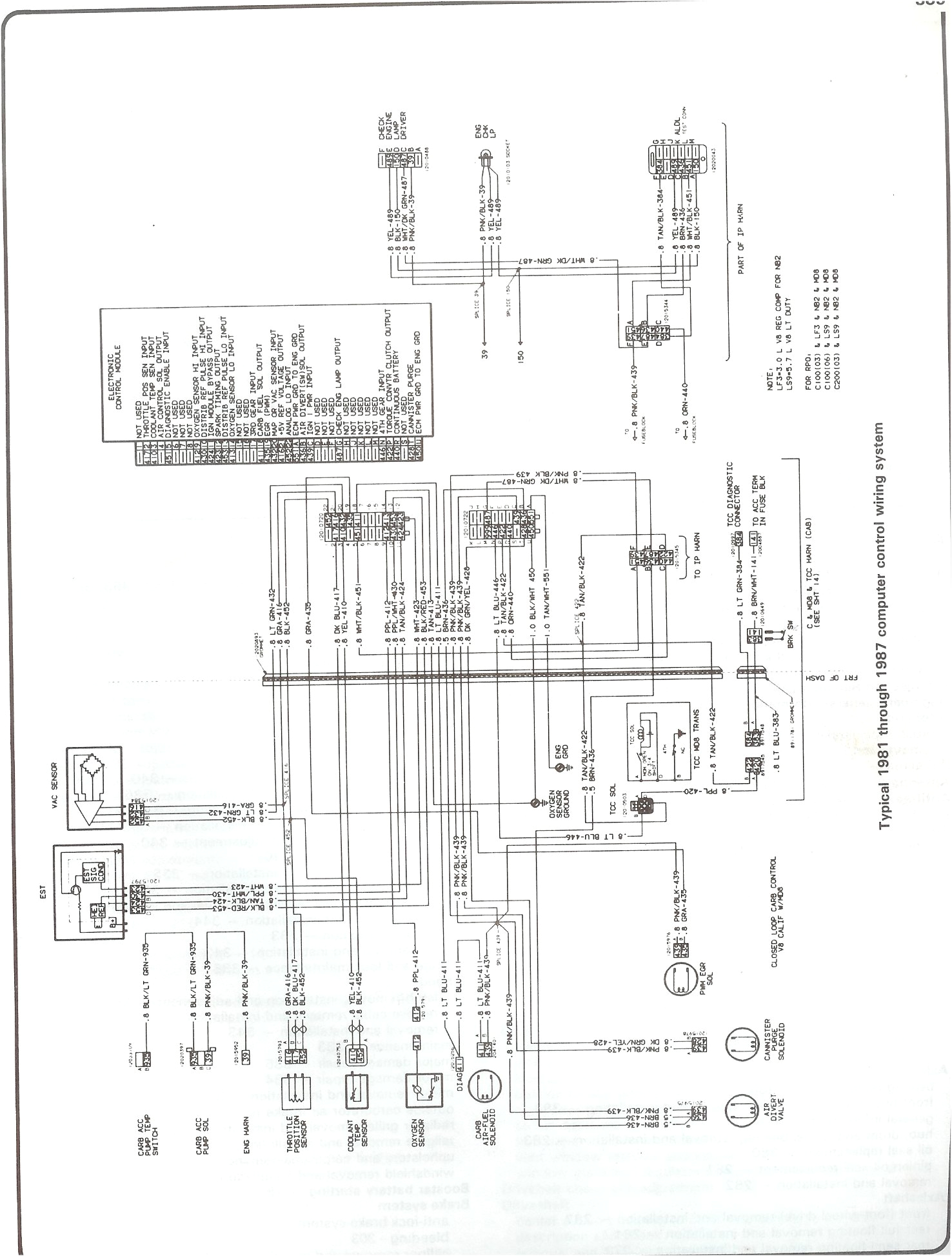
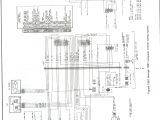
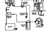
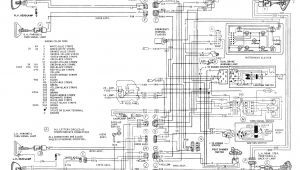
ceb885 84 chevy p30 454 wiring diagram wiring resources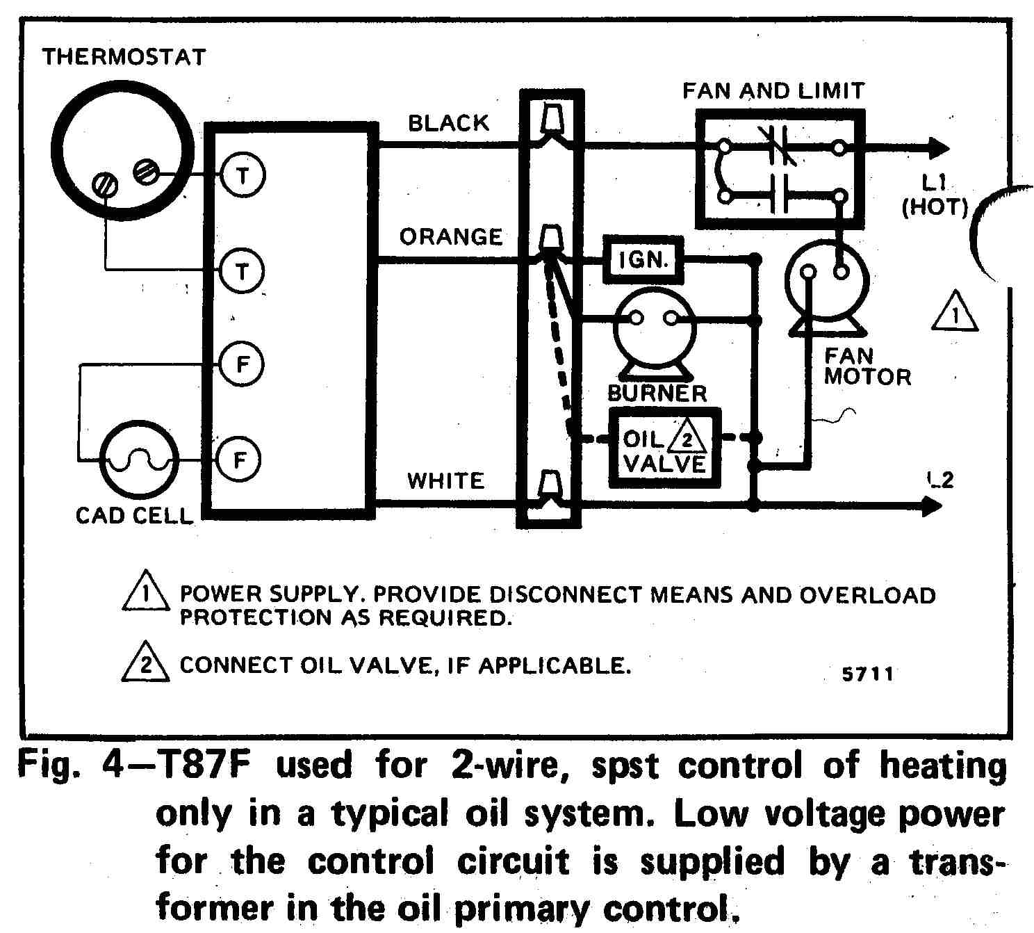
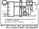
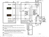
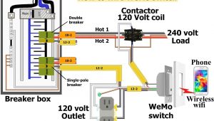
0094a honeywell fan limit switch wiring diagram digital
A set of wiring diagrams may be required by the electrical inspection authority to implement attachment of the quarters to the public electrical supply system.
Wiring diagrams will plus swell panel schedules for circuit breaker panelboards, and riser diagrams for special facilities such as flare alarm or closed circuit television or further special services.
You Might Also Like :
[gembloong_related_posts count=3]
honeywell r8239a1052 wiring diagram another photograph:
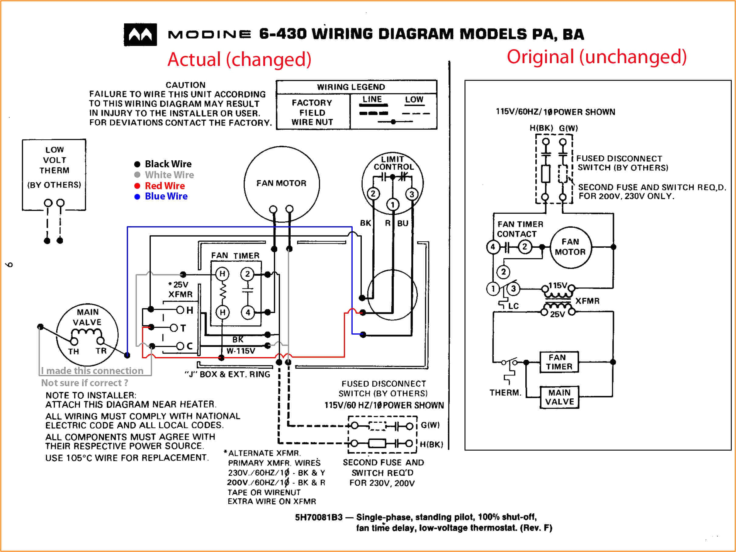
0094a honeywell fan limit switch wiring diagram digital
t6051 heavy duty line voltage thermostats manualzz com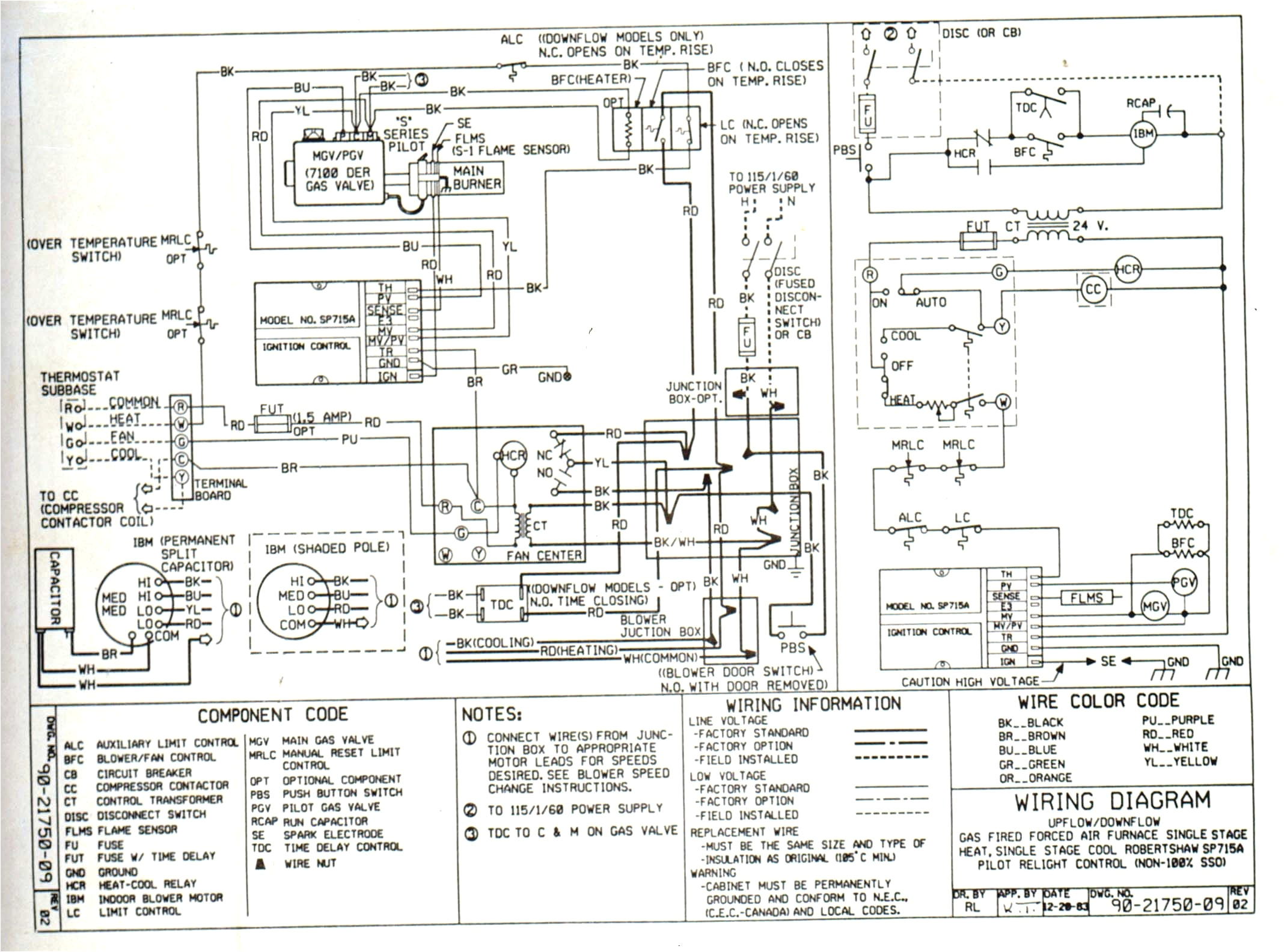
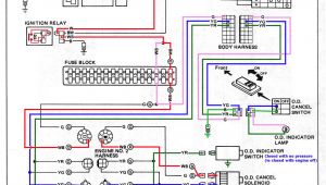
2013 mack truck fuse diagram wiring library
r8239a1052 u honeywell convenient connections for thermostat and heating and cooling equipment wiring mounts on standard 4 x 4 junction box can be mounted in any indoor location without additional enclosure relay is easily replaced without disturbing wiring includes relay enclosure r8239a1052 wiring diagram library for honeywell fan center if you like this picture please right click and save the picture thanks for visiting this website we provide a lot of options related to r8239a1052 wiring diagram library for honeywell fan center images for you do not hesitate to come back r8239a1052 wiring diagram get more from wiring diagram honeywell gas valve wiring diagram together with furnace gas valve wiring diagram honeywell aquastat wiring diagram millivolt gas valve wiring old gas furnace wiring diagram antique honeywell gas valve honeywell gas control valve tempstar gas valve w wiring diagrams honeywell home heating controls faq wiring diagram s plan pump overrun st9420 and dt92e faq wiring diagram s plan plus pump overrun st9420 and dt92e faq wiring diagram combination boiler st9120 t4 additional wiring diagrams lyric t6 additional wiring diagrams v4043 zone valve s plan operation heating controls wiring guide issue 17 need some help with wiring a honeywell r8239a1052 fan center i looked at wiring diagram but still not sure if im reading correctly i can hook up black and white to line to feed the transformer 120v i start to get confused at relay wiring red and brown go to fan motor red hi speed and brown low speed since i have an old furnace i assume one speed so cap brown wire and black wire coming out of honeywell fan center wiring diagram wiring diagram honeywell fan center wiring diagram kia speakers wiring diagram typical rv wiring diagram recessed lighting wiring diagram 1998 honda accord engine wiring diagram 2004 nissan maxima under hood fuse box peugeot 206 wiring diagrams rear windows heated window 1988 softail handlebar wiring diagram 2007 mazda 3 wiring diagram 1971 vw bus fuse box r8239a1052 honeywell r8239a1052 40 va fan center w honeywell r8239a1052 40 va fan center w spdt switching action includes r8222b include nema standard transformer for excellent voltage control provide low voltage control of line voltage fan motors and auxiliary circuits in heating cooling or heating cooling circuits features nema standard type d transformer included perfect climate confrot center control system honeywell honeywell 1885 douglas drive north minneapolis minnesota 55422 4386 800 328 5111 in canadashoneywell limited honeywell limitoe 35 dynamic drive scarborough ontario m1v 4z9 international sales and service offices in all principal cities of the world manufacturing in australia canada finland france honeywell l7224u1002 installation guide page 5 get honeywell l7224u1002 installation guide get all honeywell manuals honeywell th8320r1003 installation manual pdf download honeywell th8320r1003 installation manual visionpro 8000 with redlink wiring diagrams by system type conventional wiring diagram system type reference standard heat cool heat pump with auxiliary heat geothermal radiant heat heat pump with oil forced air backup geothermal radiant heat with geothermal forced air and backup heat using separate transformer for the radiant heat wood stove
