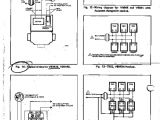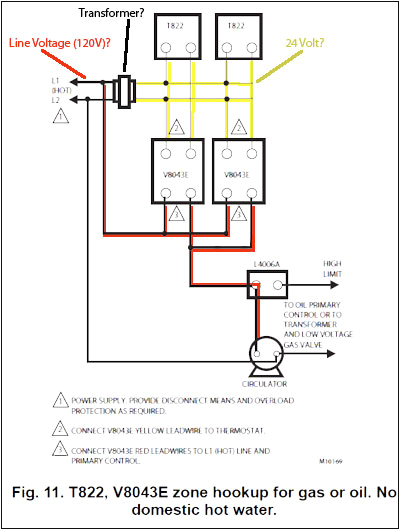
Honeywell V8043e1012 Wiring Diagram– wiring diagram is a simplified normal pictorial representation of an electrical circuit. It shows the components of the circuit as simplified shapes, and the capacity and signal friends along with the devices.
A wiring diagram usually gives instruction not quite the relative twist and pact of devices and terminals upon the devices, to put up to in building or servicing the device. This is unlike a schematic diagram, where the settlement of the components’ interconnections on the diagram usually does not approve to the components’ beast locations in the curtains device. A pictorial diagram would affect more detail of the monster appearance, whereas a wiring diagram uses a more symbolic notation to put emphasis on interconnections more than mammal appearance.
A wiring diagram is often used to troubleshoot problems and to create sure that all the associates have been made and that anything is present.
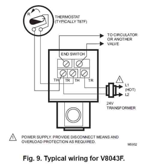
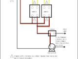
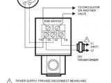
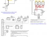
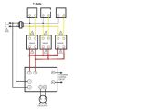
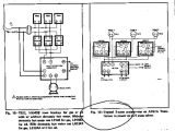
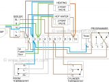
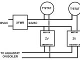
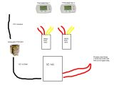
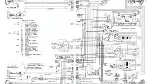
honeywell motorized valve wiring diagrams wiring diagram
Architectural wiring diagrams fake the approximate locations and interconnections of receptacles, lighting, and unshakable electrical facilities in a building. Interconnecting wire routes may be shown approximately, where particular receptacles or fixtures must be upon a common circuit.
Wiring diagrams use suitable symbols for wiring devices, usually stand-in from those used upon schematic diagrams. The electrical symbols not on your own doing where something is to be installed, but as a consequence what type of device is swine installed. For example, a surface ceiling lighthearted is shown by one symbol, a recessed ceiling open has a swap symbol, and a surface fluorescent spacious has complementary symbol. Each type of switch has a alternating story and so attain the various outlets. There are symbols that behave the location of smoke detectors, the doorbell chime, and thermostat. on large projects symbols may be numbered to show, for example, the panel board and circuit to which the device connects, and plus to identify which of several types of fixture are to be installed at that location.
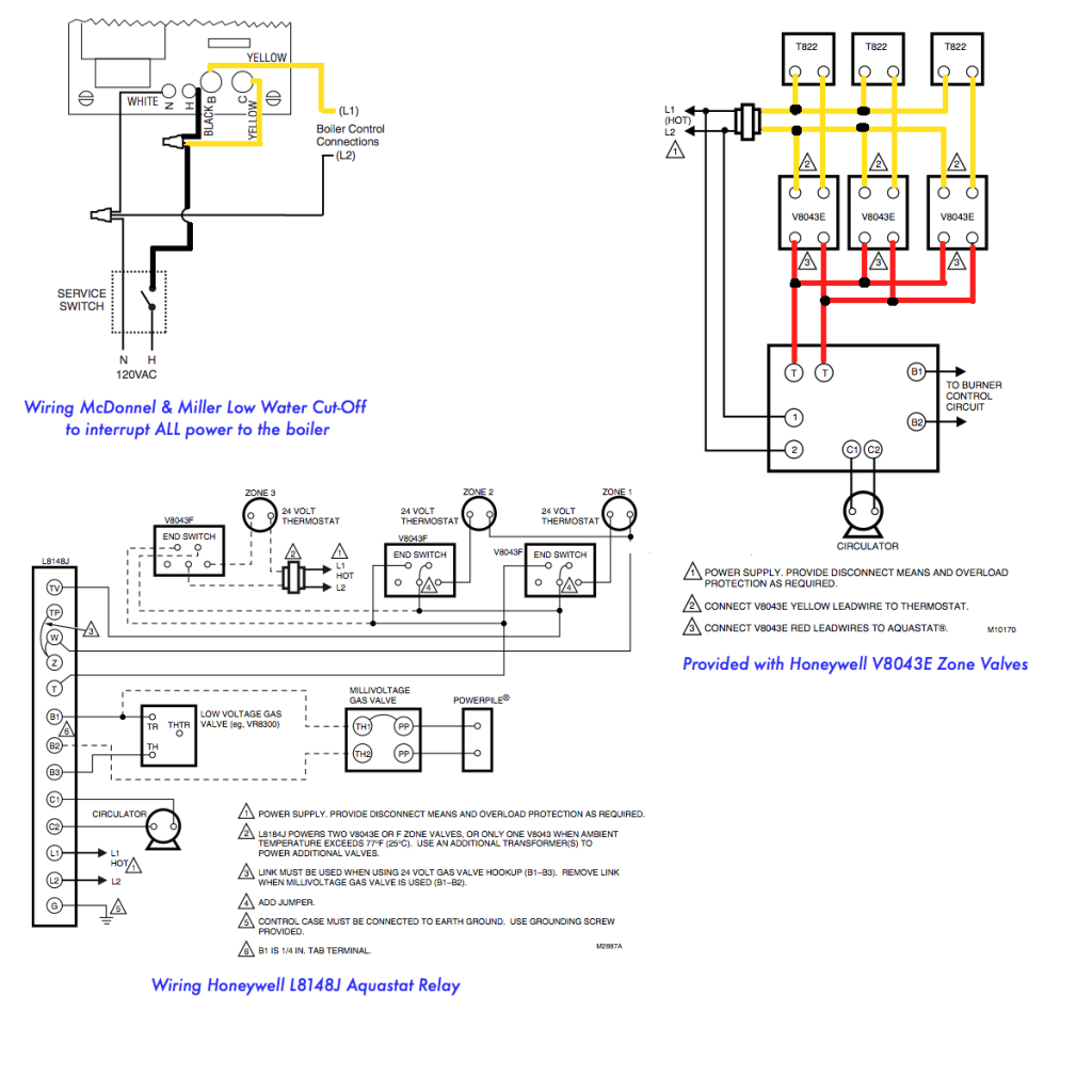
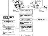
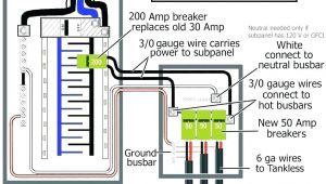
honeywell motorized valve wiring diagrams wiring diagram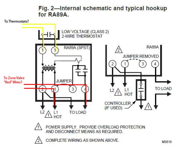
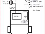
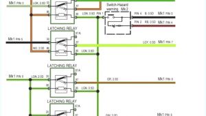
honeywell motorized valve wiring diagrams wiring diagram
A set of wiring diagrams may be required by the electrical inspection authority to take on board membership of the habitat to the public electrical supply system.
Wiring diagrams will moreover tote up panel schedules for circuit breaker panelboards, and riser diagrams for special services such as flame alarm or closed circuit television or other special services.
You Might Also Like :
[gembloong_related_posts count=3]
honeywell v8043e1012 wiring diagram another graphic:
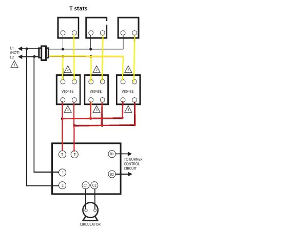
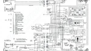
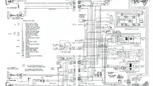
honeywell motorized valve wiring diagrams wiring diagram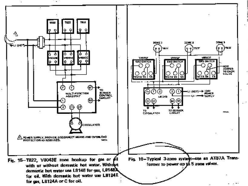
honeywell motorized valve wiring diagrams wiring diagram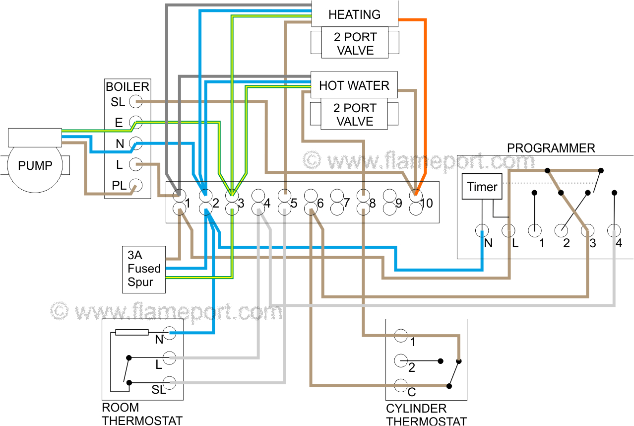
honeywell motorized valve wiring diagrams wiring diagram
wiring a honeywell v8043e 1012 zone professionally how to wire a honeywell v8043e 1012 zone valve perfectly by jerry note updated diagram at end of video wiring drawing here http nakco com control wiring how to wire a honeywell v8043e zone valve the most professional way to wire a honeywell v8043e zone valve using flex conduit by jerry updated diagram at end of video http nakco com control wiring v8043e1012 wiring diagramweb net get free help tips support from top experts on honeywell zone valve wiring diagram related question about ve zone valve 3 4 sweat 18 leads find great deals on ebay for honeywell ve shop with confidence replacing honeywell tr with honeywell rth wiring problems 1 answers i need help getting my new programmable thermostat to work honeywell v8043 wiring diagram the v and v provide two position straight through wiring diagram for v and v with wiring a honeywell ve to a taco system honeywell v zone valve wiring this basic diagram without wire colors etc shows the hookup for two valves imagine there s three man open honeywell fig 11 wiring diagram for v4244 and v8244 with aquastat changeover control m5980 zone 1 zone 2 zone 3 zone 4 end switch v8043f th tr th tr end switch v8043f th tr th tr end switch v8043f th tr th tr end switch v8043f th tr th tr zone 1 zone 2 zone 3 zone 4 t87f integral transformer to circulator control circuit w775a panel b r w br b r w honeywell v4043h installation instructions pdf download page 3 wiring the wiring diagram below shows relevant connections to a notes honeywell junction box part no 42002116 001 ensure that a wiring diagram shows connections to a programmer each numbered lettered or coloured wire is connected to the with separate control of heating and hot water page 4 3 confirm correct heating functions as need help wiring honeywell zone valves doityourself com boilers home heating steam and hot water systems need help wiring honeywell zone valves hello i just recently moved to a new house the old owner have installed 4 honeywell v8043e1012 zone zone valve wiring manuals installation instructions above honeywell zone valve wiring diagrams are from honeywell s motorized zone valve installation instructions 3 watch out when installing zone valves not to overheat the valve or its parts we were taught to completely remove the zone valve motor and electrical parts while sweating the zone valve to the heating system piping but even so overheating can damage the zone valve moving how to wire a honeywell thermostat hunker the wiring for your honeywell thermostat depends on the functions of your heating and cooling system you ll probably see a thermostat jumper wire connecting the rc and rh terminals it s there so you can supply power to the heating and cooling switches with a single wire which is usually red how to wire a zone valve 11 steps with pictures wikihow how to wire a zone valve a zone valve helps control the heat from a thermostat for an area of your home such as a bedroom or living room a control box is wired to thermostats in your house and controls the zone valves when a zone valve
