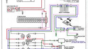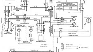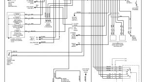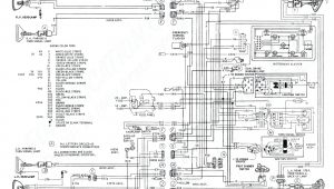
Hopkins Impulse Brake Controller Wiring Diagram– wiring diagram is a simplified welcome pictorial representation of an electrical circuit. It shows the components of the circuit as simplified shapes, and the capability and signal connections amid the devices.
A wiring diagram usually gives recommendation very nearly the relative position and accord of devices and terminals on the devices, to incite in building or servicing the device. This is unlike a schematic diagram, where the covenant of the components’ interconnections upon the diagram usually does not allow to the components’ visceral locations in the curtains device. A pictorial diagram would exploit more detail of the monster appearance, whereas a wiring diagram uses a more symbolic notation to draw attention to interconnections more than mammal appearance.
A wiring diagram is often used to troubleshoot problems and to make clear that every the contacts have been made and that all is present.
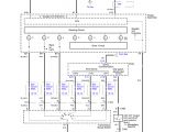
draw tite brake controller wiring diagram gone fuse6
Architectural wiring diagrams play the approximate locations and interconnections of receptacles, lighting, and surviving electrical services in a building. Interconnecting wire routes may be shown approximately, where particular receptacles or fixtures must be upon a common circuit.
Wiring diagrams use standard symbols for wiring devices, usually interchange from those used upon schematic diagrams. The electrical symbols not deserted operate where something is to be installed, but as well as what type of device is mammal installed. For example, a surface ceiling roomy is shown by one symbol, a recessed ceiling well-ventilated has a interchange symbol, and a surface fluorescent lively has different symbol. Each type of switch has a swing story and so get the various outlets. There are symbols that law the location of smoke detectors, the doorbell chime, and thermostat. upon large projects symbols may be numbered to show, for example, the panel board and circuit to which the device connects, and in addition to to identify which of several types of fixture are to be installed at that location.
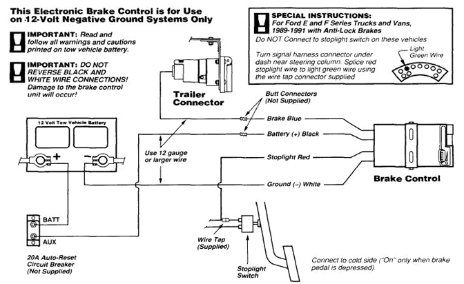
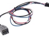
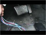
ford brake control wiring harness many balmoond19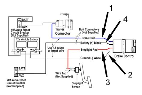
draw tite brake controller wiring diagram gone fuse6
A set of wiring diagrams may be required by the electrical inspection authority to espouse attachment of the address to the public electrical supply system.
Wiring diagrams will along with insert panel schedules for circuit breaker panelboards, and riser diagrams for special facilities such as flare alarm or closed circuit television or other special services.
You Might Also Like :
[gembloong_related_posts count=3]
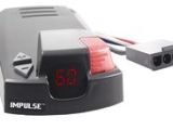
hopkins impulse brake controller wiring diagram another picture:
175 hopkins trailer plug wiring diagram manual wiring library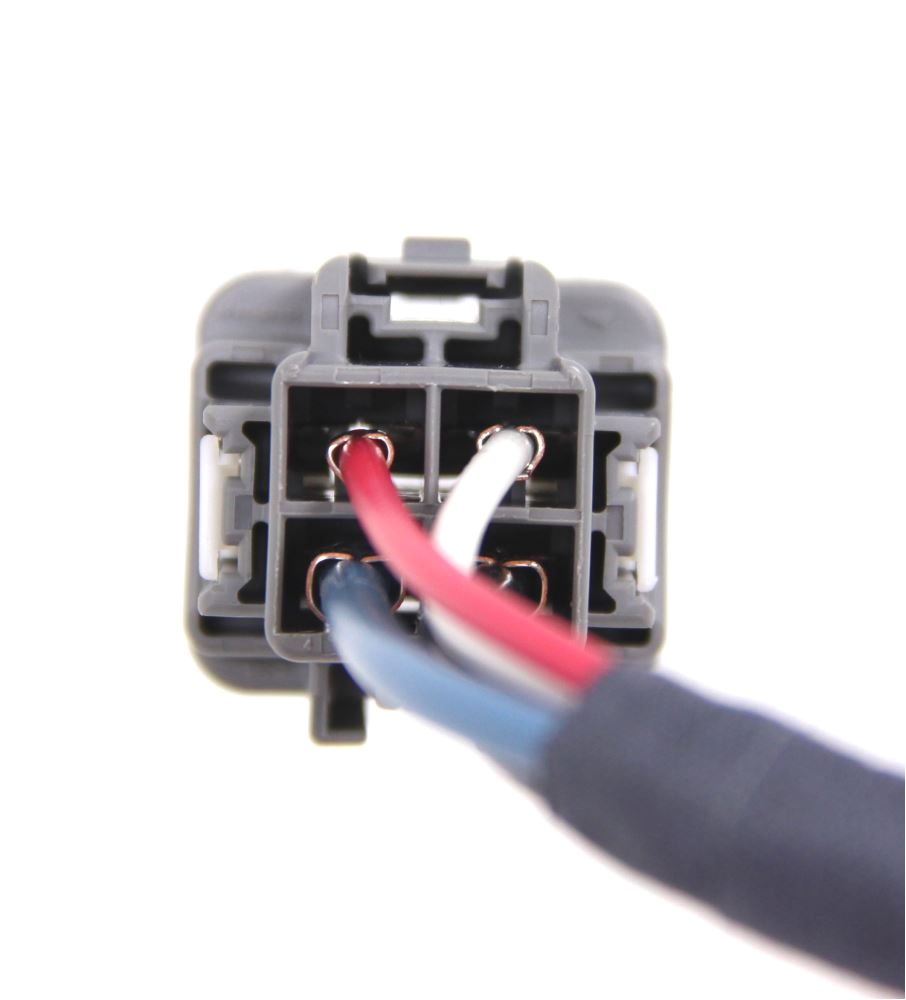
2019 ram 1500 hopkins plug in simple custom wiring adapter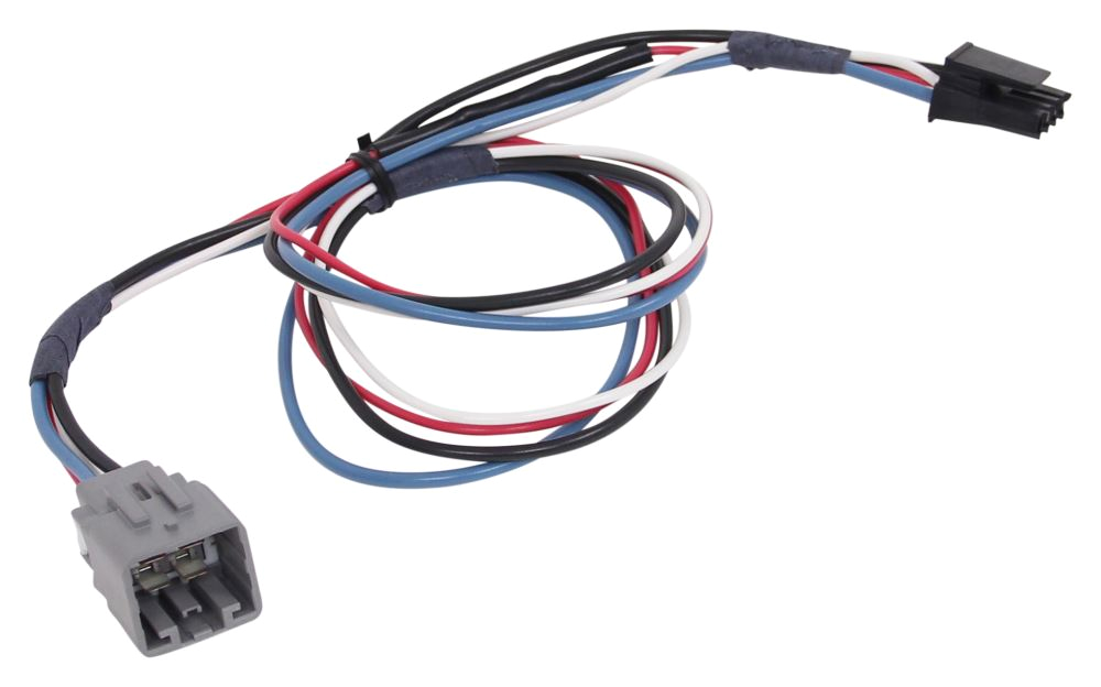
2019 ram 1500 hopkins plug in simple custom wiring adapter
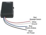
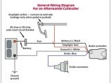
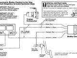
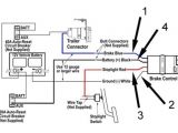
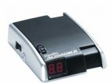
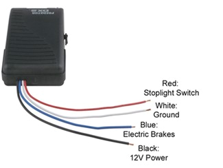
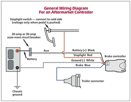
hopkins impulse brake controller wiring diagram wiring harness to install hopkins impulse brake controller in a toyota i have a toyota 4runner and an hopkins impulse break controller i just need to wiring diagram to install hopkins proportional brake controller in a from to gm trucks did not use plug in style brake controller wiring instead they had 4 sometimes 5 blunt cut wires bundled up under the drivers wiring diagram to install impulse trailer brake controller wiring diagram trailer impulse trailer brake controller wiring diagram hopkins impulse trailer brake controller wiring diagram impulse trailer brake controller wiring diagram folks understand that trailer is a car comprised of very complicated mechanics this car is designed not just to travel one place to another but also to take heavy loads this article will be discussing impulse trailer brake controller hopkins impulse brake controller wiring diagram impulse brake controller wiring diagram if you like this picture please right click and save the picture thanks for visiting this website we provide a lot of options related to tekonsha prodigy p3 brake controller wiring diagram impulse cute and images for you do not hopkins impulse brake control hopkins trailer brake control wiring out hopkins impulse trailer brake controller wiring diagram hopkins impulse trailer brake controller wiring diagram wiring diagram impulse trailer brake controller wiring diagram by bang mus published february 12 2019 full size is 2338 1700 pixels impulse universal installation hopkins towing solutions universal installation white wire ground negative terminal on battery blue wire trailer electric brakes black wire positive terminal on battery red wire cold side of stop lamp switch or brake light caution wire colors vary by manufacturer be sure to wire by function only vehicle manufacturer wiring codes brake conrol wire blueblack lred whiteteam can assist you doc hopkins brake controller wiring diagram hopkins brake controller wiring diagram is affable in our digital library an online admission to it is set as public for that reason you can download it instantly our digital library saves in fused countries allowing you to acquire the most less latency times to download any of our books taking into consideration this one merely said the hopkins brake controller wiring diagram is hopkins impulse trailer brake controller wiring diagram impulse trailer brake controller wiring diagram hopkins impulse trailer brake controller wiring diagram impulse trailer brake controller wiring diagram folks understand that trailer is a car comprised of very complicated mechanics this car is designed not just to travel one place to another but download hopkins brake controller wiring diagram hopkins brake controller wiring diagram hopkins brake controller wiring diagram if you ally infatuation such a referred hopkins brake controller wiring diagram ebook that will allow you worth get the completely best seller from us currently from several preferred authors if you want to comical books lots of novels tale jokes and impulse brake control hopkins towing solutions the 47235 brake control utilizes time based actuation for applying braking power to the trailer brakes the built in digital display makes it easy for setting braking intensity the braking force to the trailer can easily be adjusted from 5 to 99 for setting the exact percentage of brake power desired most states and provinces require a trailer brake controller based on the weight of the wiring guides hopkins towing solutions wiring guides note identify the wires on your vehicle and trailer by function only color coding is not standard among all manufacturers refer to product instructions and locate wires on vehicle by function only not all vehicles are listed obove recommended use with 47295 and 47285
