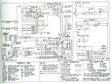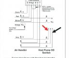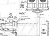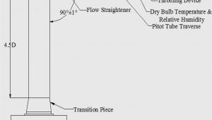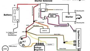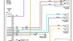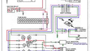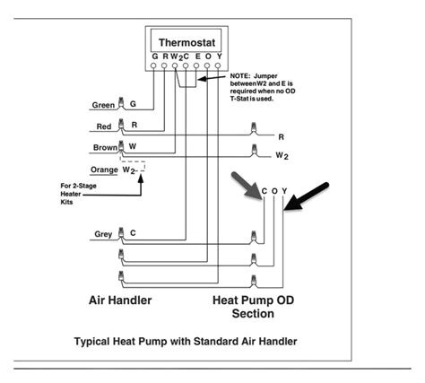
Hvac Transformer Wiring Diagram– wiring diagram is a simplified good enough pictorial representation of an electrical circuit. It shows the components of the circuit as simplified shapes, and the knack and signal links with the devices.
A wiring diagram usually gives guidance virtually the relative twist and covenant of devices and terminals upon the devices, to support in building or servicing the device. This is unlike a schematic diagram, where the contract of the components’ interconnections on the diagram usually does not grant to the components’ mammal locations in the the end device. A pictorial diagram would play in more detail of the monster appearance, whereas a wiring diagram uses a more symbolic notation to draw attention to interconnections greater than creature appearance.
A wiring diagram is often used to troubleshoot problems and to create definite that every the contacts have been made and that whatever is present.
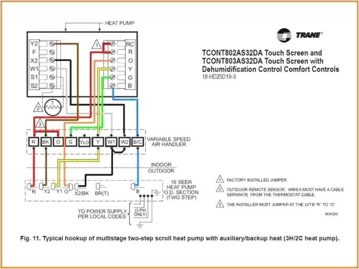
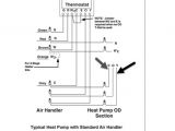
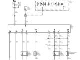
auxillary transformer oil furnace thermostat wiring wiring diagram
Architectural wiring diagrams decree the approximate locations and interconnections of receptacles, lighting, and steadfast electrical services in a building. Interconnecting wire routes may be shown approximately, where particular receptacles or fixtures must be on a common circuit.
Wiring diagrams use gratifying symbols for wiring devices, usually rotate from those used on schematic diagrams. The electrical symbols not and no-one else perform where something is to be installed, but furthermore what type of device is visceral installed. For example, a surface ceiling roomy is shown by one symbol, a recessed ceiling spacious has a stand-in symbol, and a surface fluorescent light has option symbol. Each type of switch has a alternating parable and for that reason do the various outlets. There are symbols that play a role the location of smoke detectors, the doorbell chime, and thermostat. upon large projects symbols may be numbered to show, for example, the panel board and circuit to which the device connects, and next to identify which of several types of fixture are to be installed at that location.
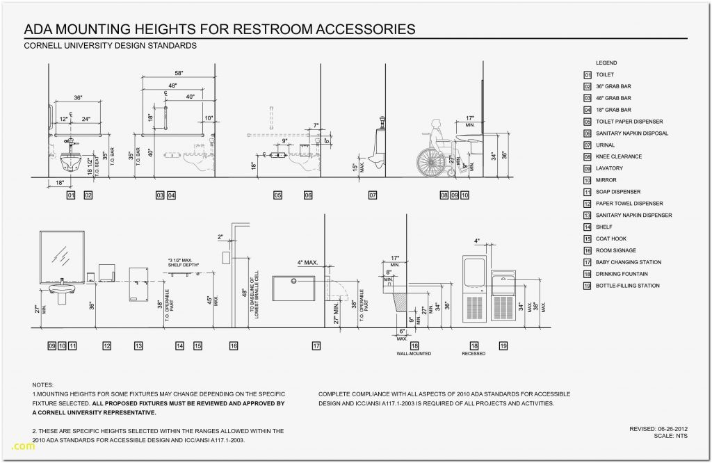
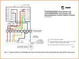
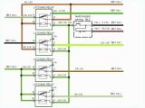
what is hvac potight
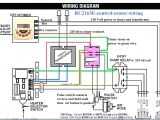
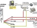
480v to 120v transformer wiring diagram wiring diagram centre
A set of wiring diagrams may be required by the electrical inspection authority to espouse link of the habitat to the public electrical supply system.
Wiring diagrams will then append panel schedules for circuit breaker panelboards, and riser diagrams for special facilities such as blaze alarm or closed circuit television or other special services.
You Might Also Like :
- Hitachi Lr180 03c Alternator Wiring Diagram
- Aem Wideband O2 Sensor Wiring Diagram
- 1996 F250 Stereo Wiring Diagram
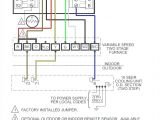
hvac transformer wiring diagram another picture:
what is hvac potight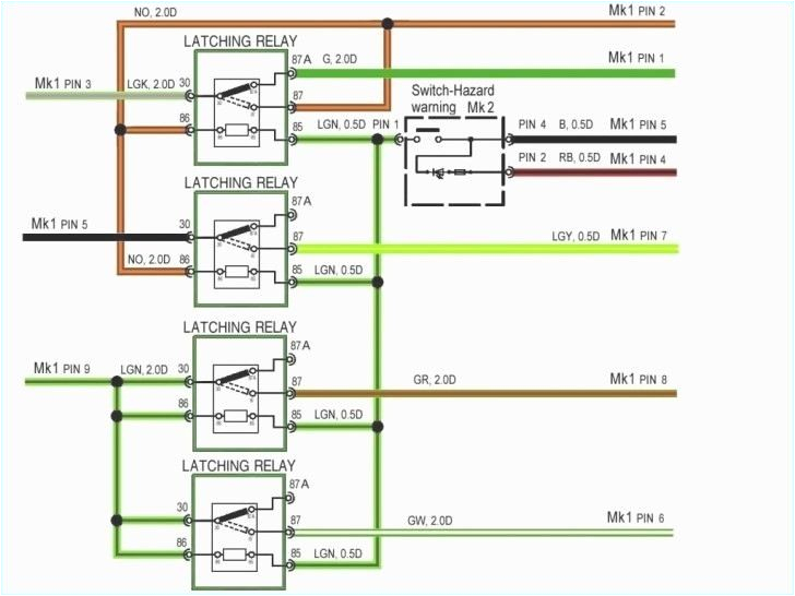
what is hvac potight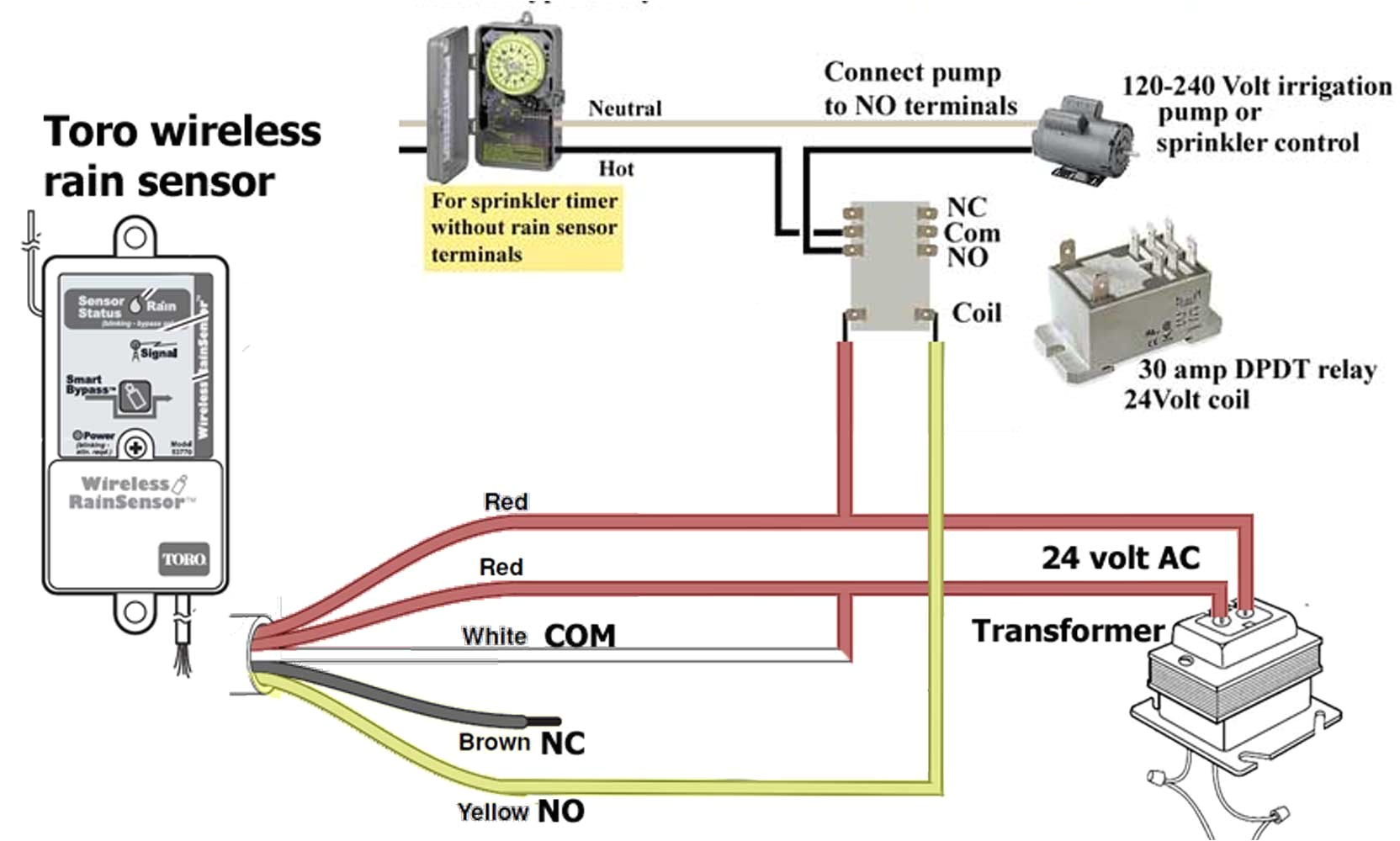
480v to 120v transformer wiring diagram wiring diagram centre
hvac transformer wiring diagram free wiring diagram variety of hvac transformer wiring diagram a wiring diagram is a streamlined conventional pictorial representation of an electric circuit it reveals the parts of the circuit as streamlined shapes as well as the power and signal links in between the tools hvac transformer wiring diagram gallery wiring collection hvac transformer wiring diagram what s wiring diagram a wiring diagram is a kind of schematic which utilizes abstract photographic icons to reveal all the affiliations of parts in a system understanding electrical schematics part 1 revised there are three basic types of wiring diagrams used in the hvac r industrytoday the first and most common is the ladder diagram so called because it looks like the symbols that are used to represent the components in the system have been placed on the rungs of a ladder from this point forward ladder dia grams will be referred to as schematic diagrams or simply schematics a hvac transformer wiring diagram download faceitsalon com hvac transformer wiring diagram download hvac transformer wiring diagram wire diagram 12v transformer wiring diagram keyless entry installation wire diagram lovely trane air conditioner 120v to 24v transformer wiring diagram furnace 24 volt in arresting hvac transformer wiring wiring diagram pictures hvac transformer wiring jun 20 2019 this amazing photo selections about hvac transformer wiring is available to download we collect this amazing photo from internet and select the best for you hvac transformer wiring diagram wiring diagram and hvac transformer wiring diagram here you are at our site this is images about hvac transformer wiring diagram posted by benson fannie in hvac category on jun 25 2019 electrical wiring diagrams for air conditioning systems usually the electrical wiring diagram of any hvac equipment can be acquired from the manufacturer of this equipment who provides the electrical wiring diagram in the user s manual see fig 1 or sometimes on the equipment itself see fig 2 hvac furnace control board wiring in this video i show where all the wires go on this bryant furnace control board thanks for watching please consider clicking below to help support our channel so we may keep bringing you the hvac transformer i discuss the low voltage transformer design for heating and air conditioning systems the 24v transformer is used on most residential and commercial systems for thermostat power
