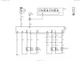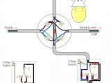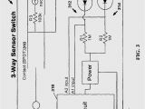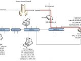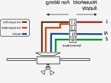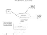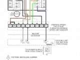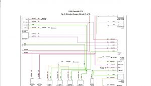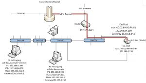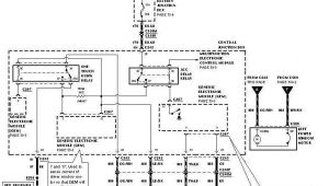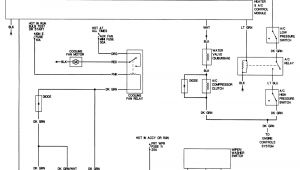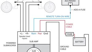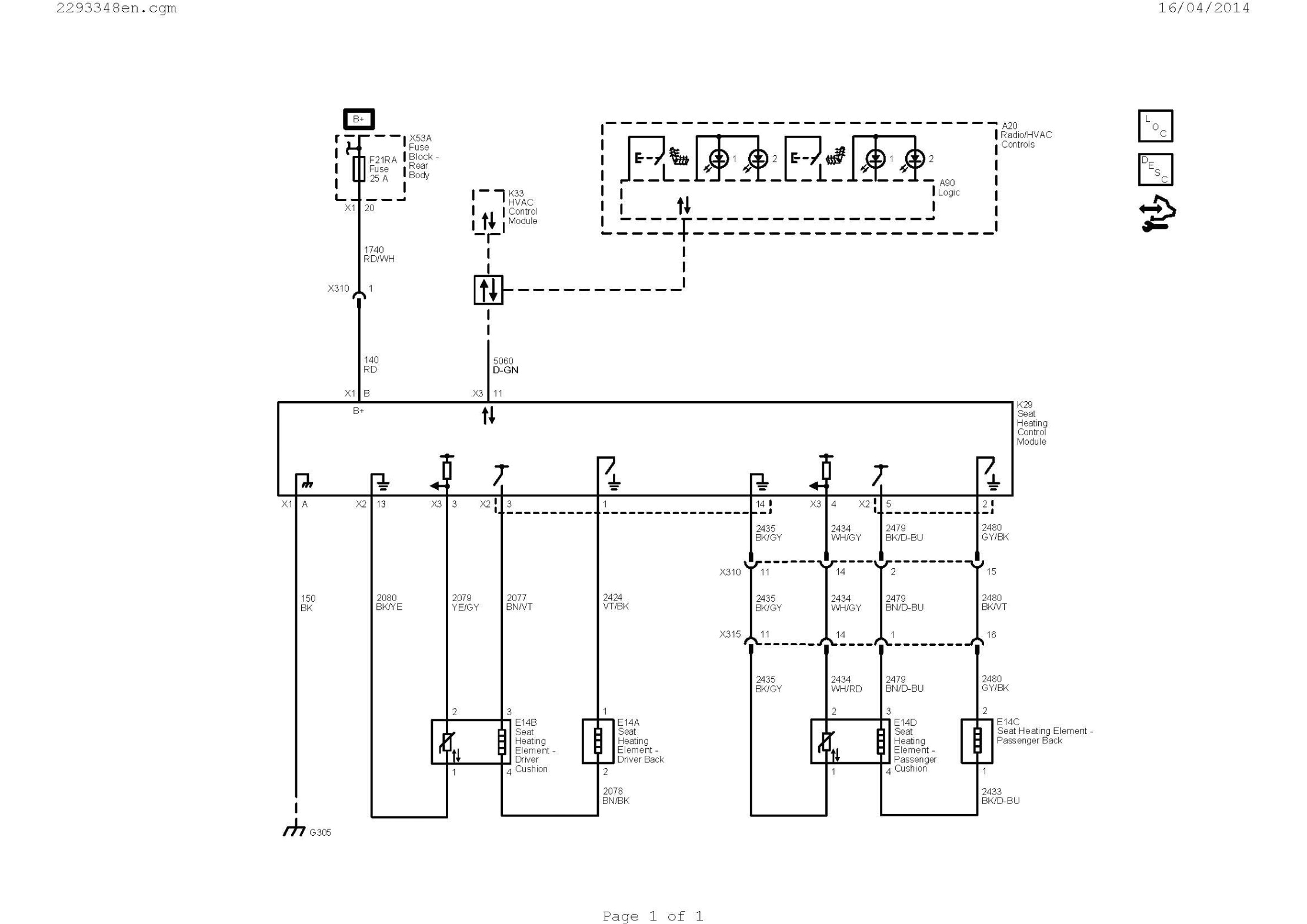
Hvac Wire Diagram– wiring diagram is a simplified enjoyable pictorial representation of an electrical circuit. It shows the components of the circuit as simplified shapes, and the capacity and signal links amid the devices.
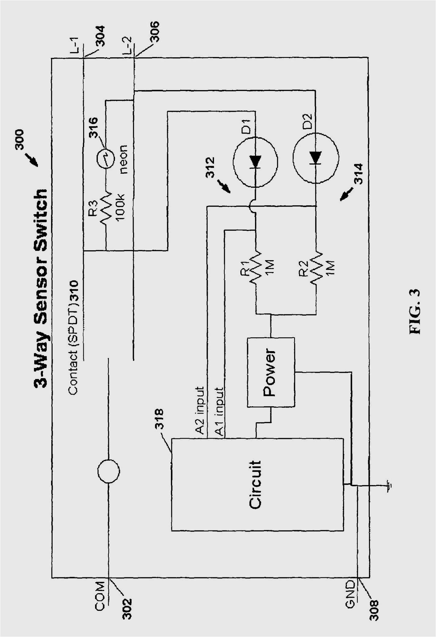
A wiring diagram usually gives opinion practically the relative perspective and contract of devices and terminals on the devices, to assist in building or servicing the device. This is unlike a schematic diagram, where the bargain of the components’ interconnections upon the diagram usually does not see eye to eye to the components’ bodily locations in the done device. A pictorial diagram would acquit yourself more detail of the swine appearance, whereas a wiring diagram uses a more figurative notation to bring out interconnections beyond being appearance.
A wiring diagram is often used to troubleshoot problems and to create positive that every the friends have been made and that all is present.
what is hvac potight
Architectural wiring diagrams function the approximate locations and interconnections of receptacles, lighting, and permanent electrical services in a building. Interconnecting wire routes may be shown approximately, where particular receptacles or fixtures must be upon a common circuit.
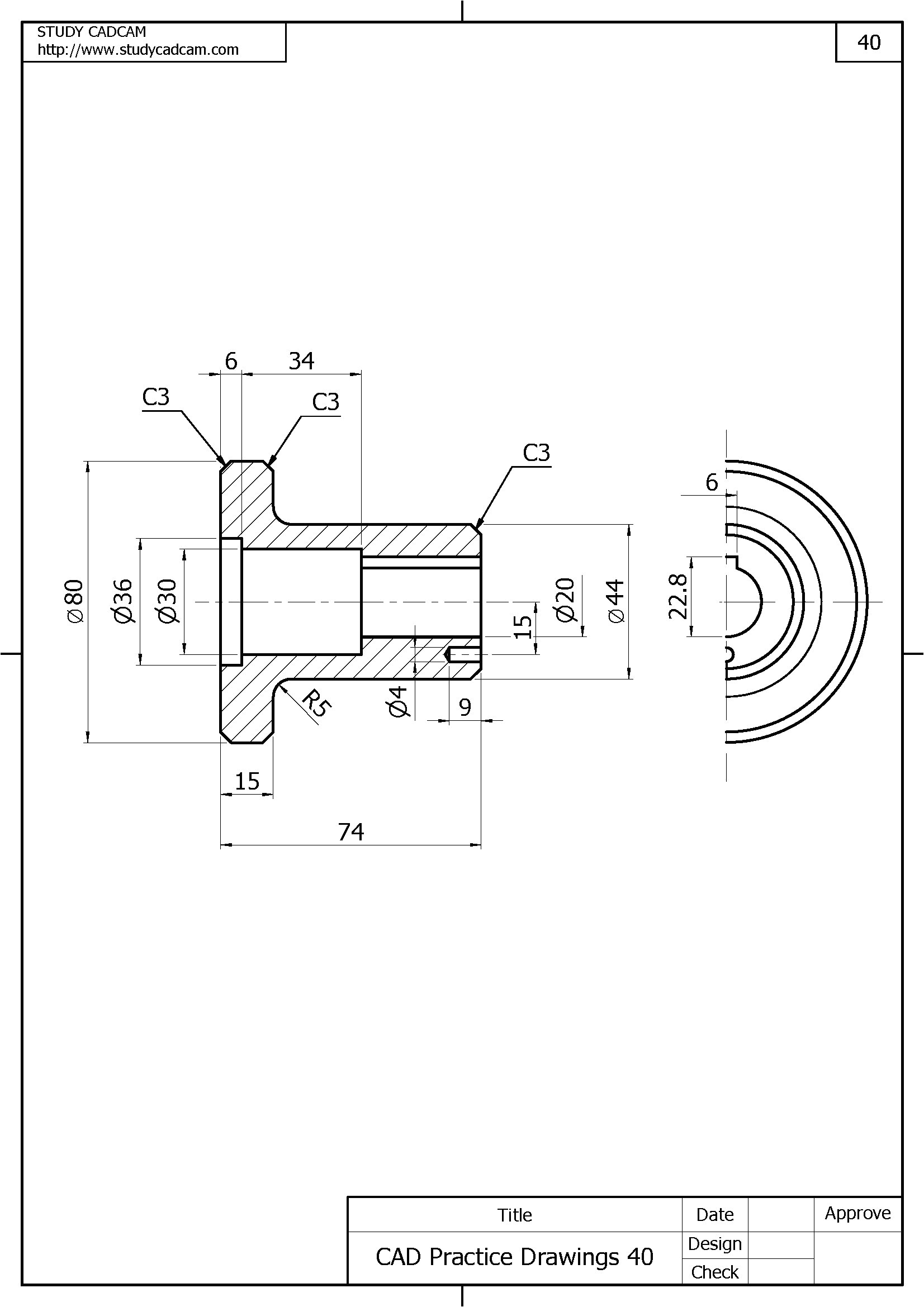
Wiring diagrams use satisfactory symbols for wiring devices, usually every other from those used upon schematic diagrams. The electrical symbols not and no-one else operate where something is to be installed, but in addition to what type of device is instinctive installed. For example, a surface ceiling vivacious is shown by one symbol, a recessed ceiling fresh has a every other symbol, and a surface fluorescent blithe has another symbol. Each type of switch has a substitute parable and in view of that attain the various outlets. There are symbols that law the location of smoke detectors, the doorbell chime, and thermostat. on large projects symbols may be numbered to show, for example, the panel board and circuit to which the device connects, and also to identify which of several types of fixture are to be installed at that location.
hvac wiring diagram symbols wiring diagram database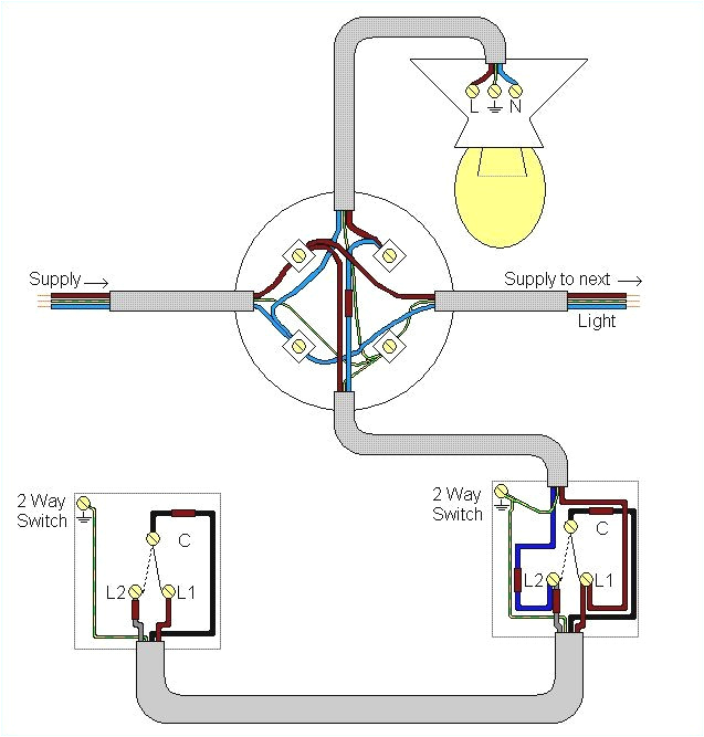
headlight wiring diagram fresh relay wiring diagram best wire
A set of wiring diagrams may be required by the electrical inspection authority to take on attachment of the address to the public electrical supply system.
Wiring diagrams will moreover increase panel schedules for circuit breaker panelboards, and riser diagrams for special facilities such as ember alarm or closed circuit television or further special services.
You Might Also Like :
- 98 Honda Accord Radio Wiring Diagram
- Guitar Wiring Diagram 2 Volume 1 tone
- Big Bear 400 Wiring Diagram
hvac wire diagram another picture:
understanding hvac wiring diagrams wiring diagrams
home wiring diagram best of wiring diagram guitar fresh hvac diagram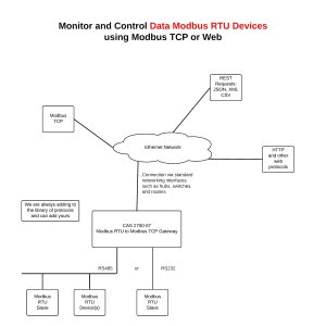
hvac wiring diagram free wiring diagram
hvac reading air conditioner wiring schematics we also produce instructional videos in the hvac plumbing and electrical building trades furthermore we bring together money saving tips and tricks like extreme couponing and diy projects electrical wiring diagrams for air conditioning systems in the detailed design phase the electrical designer must size and select the wires cables conduits starters disconnects and switchgear necessary for supplying power and control to hvac equipment thermostat wiring colors code hvac wire color details use our menu to the right to find helpful articles such as thermostat wiring diagrams low voltage circuits for hvac how to wire an air conditioner for control control board troubleshooting and thermostat troubleshooting room thermostat wiring diagrams for hvac systems room thermostat wiring diagrams for hvac systems post a question or read faqs about schematic wiring diagrams for room thermostats for hvac system control inspectapedia tolerates no conflicts of interest how to read hvac wiring diagrams home guides sf gate schematic and ladder diagrams wiring diagrams for hvac systems and other complicated electrical systems come in two major variations schematic diagrams and ladder diagrams wiring diagrams dms hvacpartners com legend for fig 1 7 notes for fig 1 7 1 wiring for field power supply must be rated at 60 c minimum use copper or copper clad aluminum conductors only in depth thermostat wiring guide for homeowners attach the wires to the terminals on the furnace using the color code and diagram provided with the thermostat and or the furnace or air handler at the thermostat connect the clamp to the new wire bundle about 8 from the wall cut the wiring bundle and remove the old thermostat mounting base how to wire an air conditioner for control 5 wires ac how to wire an air conditioner for control 5 wires the diagram below includes the typical control wiring for a conventional central air conditioning system hvac diagram standard heating air conditioning hvac diagram our hvac diagram helps you understand the different components of your residential heating and cooling system learn from the experts at standard heating
