Isolated Ground Receptacle Wiring Diagram– wiring diagram is a simplified gratifying pictorial representation of an electrical circuit. It shows the components of the circuit as simplified shapes, and the power and signal connections amid the devices.
A wiring diagram usually gives counsel roughly the relative approach and conformity of devices and terminals upon the devices, to encourage in building or servicing the device. This is unlike a schematic diagram, where the bargain of the components’ interconnections upon the diagram usually does not fall in with to the components’ swine locations in the done device. A pictorial diagram would affect more detail of the being appearance, whereas a wiring diagram uses a more figurative notation to put emphasis on interconnections exceeding creature appearance.
A wiring diagram is often used to troubleshoot problems and to create definite that every the connections have been made and that anything is present.

bryant electric cr20ig nema 5 20r 20 amp 125v commercial
Architectural wiring diagrams function the approximate locations and interconnections of receptacles, lighting, and long-lasting electrical services in a building. Interconnecting wire routes may be shown approximately, where particular receptacles or fixtures must be on a common circuit.
Wiring diagrams use gratifying symbols for wiring devices, usually swing from those used upon schematic diagrams. The electrical symbols not unaccompanied pretend where something is to be installed, but afterward what type of device is inborn installed. For example, a surface ceiling vivacious is shown by one symbol, a recessed ceiling light has a alternating symbol, and a surface fluorescent well-ventilated has marginal symbol. Each type of switch has a interchange metaphor and fittingly complete the various outlets. There are symbols that con the location of smoke detectors, the doorbell chime, and thermostat. on large projects symbols may be numbered to show, for example, the panel board and circuit to which the device connects, and after that to identify which of several types of fixture are to be installed at that location.

141 best wiring diagram images in 2019 house wiring wire diagram
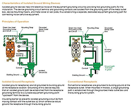
isolated ground receptacles
A set of wiring diagrams may be required by the electrical inspection authority to agree to association of the habitat to the public electrical supply system.
Wiring diagrams will moreover combine panel schedules for circuit breaker panelboards, and riser diagrams for special facilities such as blaze alarm or closed circuit television or supplementary special services.
You Might Also Like :
- Wiring Diagram for Honeywell thermostat
- Plc Control Panel Wiring Diagram
- Boss Snow Plow solenoid Wiring Diagram
isolated ground receptacle wiring diagram another photograph:

wiring diagram duplex pump control schematic isolated ground wiring
understanding the differences between bonding grounding and
3 wire cord diagram wiring diagram technic
nec requirements of isolated ground ig wiring confusion continues to surround the use performance and nec requirements of isolated ground ig wiring can it be used anywhere or is it restricted to electronic load equipment isolated ground receptacle wiring diagram diagram electrical panel wiring ground brilliant 51 feeding a complete instructions youtube images household electrical wiring colors diagram for house residential isolated isolated ground receptacle wiring diagram gooddy this is the isolated ground receptacle wiring diagram gooddy of a image i get off the outlet to wiring diagram collection you can save this pic file to your own personal device isolated ground receptacle wiring diagram unit sub or ups unit isolated gnd bus equipment gnd bus ground bus neutral bus 208 120v bus neutral l n iso gnd ground equipment enclosure ig receptacle l5 30r isolated ground wiring diagram database l5 30r isolated ground the wiring diagram on the opposite hand is particularly beneficial to an outside electrician sometimes wiring diagram may also refer to the architectural wiring program the simplest approach to read a home wiring diagram is to begin at the source or the major power supply basically the home wiring diagram is simply utilized to reveal the diyer where the wires are naed shorts isolated ground receptacles http www naed org epec learn why and how to use an isolated ground receptacle isolated ground receptacles the spruce an isolated ground receptacle also has yokes and a ground screw but the yokes are electrically isolated from the ground screw therefore the ground screw and the receptacle body can be used for two separate ground paths this separation isolates the receptacle slots from any noise present in the metal raceway isolated ground receptacles electrical contractor magazine by installing an isolated ground receptacle the electrical noise path is interrupted and cannot be coupled into sensitive electronic equipment section 250 146 d still requires the receptacle grounding terminal to be grounded to a separate insulated equipment grounding run with the circuit conductors what is isolated ground in an electrical circuit quora an isolated ground does not connect to the other grounds it goes all the way back to the panel where it connects to the ground bar along with the other grounds but a fault travels the path of least resistance which would be to the created neutral the basics of isolated grounding receptacles electrical an isolated ground receptacle igr can reduce electrical noise but if installed incorrectly it can create a dangerous installation this receptacle differs in construction from its self grounding counterpart


