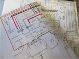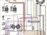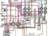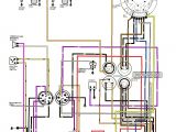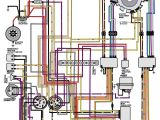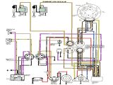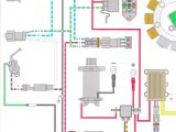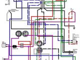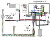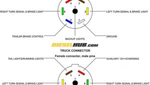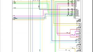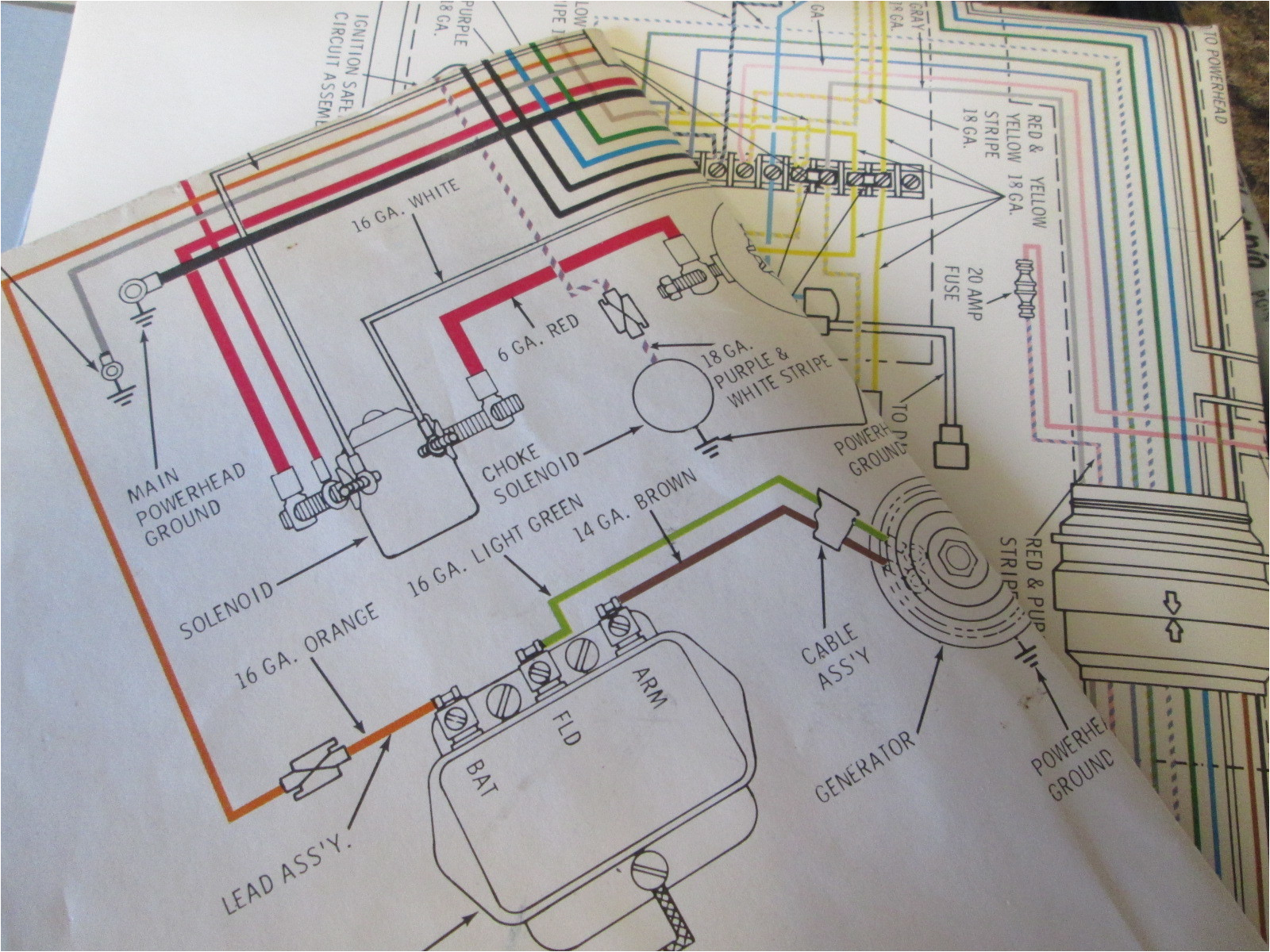
Johnson 115 Outboard Wiring Diagram– wiring diagram is a simplified all right pictorial representation of an electrical circuit. It shows the components of the circuit as simplified shapes, and the power and signal friends amid the devices.
A wiring diagram usually gives information not quite the relative perspective and covenant of devices and terminals on the devices, to back up in building or servicing the device. This is unlike a schematic diagram, where the pact of the components’ interconnections upon the diagram usually does not correspond to the components’ mammal locations in the curtains device. A pictorial diagram would feat more detail of the living thing appearance, whereas a wiring diagram uses a more symbolic notation to heighten interconnections higher than beast appearance.
A wiring diagram is often used to troubleshoot problems and to create clear that every the links have been made and that all is present.
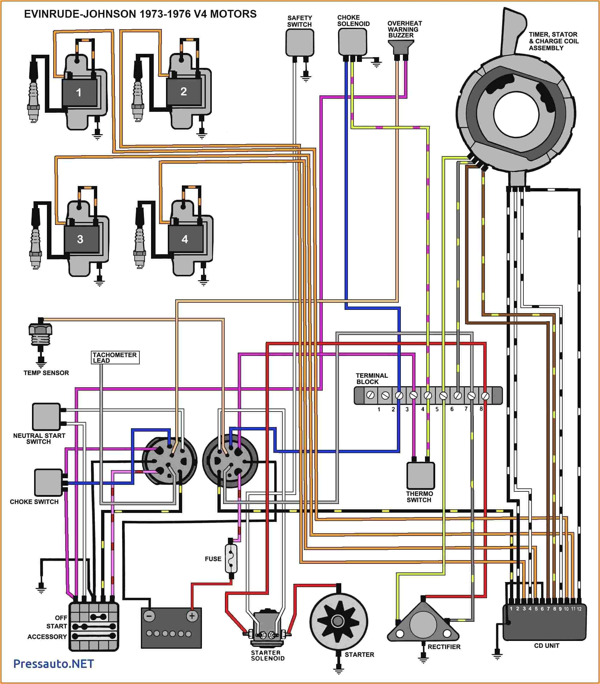
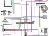
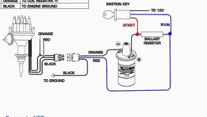
johnson outboard ignition switch wiring diagram free
Architectural wiring diagrams feign the approximate locations and interconnections of receptacles, lighting, and remaining electrical facilities in a building. Interconnecting wire routes may be shown approximately, where particular receptacles or fixtures must be on a common circuit.
Wiring diagrams use agreeable symbols for wiring devices, usually different from those used on schematic diagrams. The electrical symbols not only produce an effect where something is to be installed, but afterward what type of device is brute installed. For example, a surface ceiling roomy is shown by one symbol, a recessed ceiling light has a vary symbol, and a surface fluorescent vivacious has unorthodox symbol. Each type of switch has a alternative tale and thus complete the various outlets. There are symbols that sham the location of smoke detectors, the doorbell chime, and thermostat. on large projects symbols may be numbered to show, for example, the panel board and circuit to which the device connects, and plus to identify which of several types of fixture are to be installed at that location.
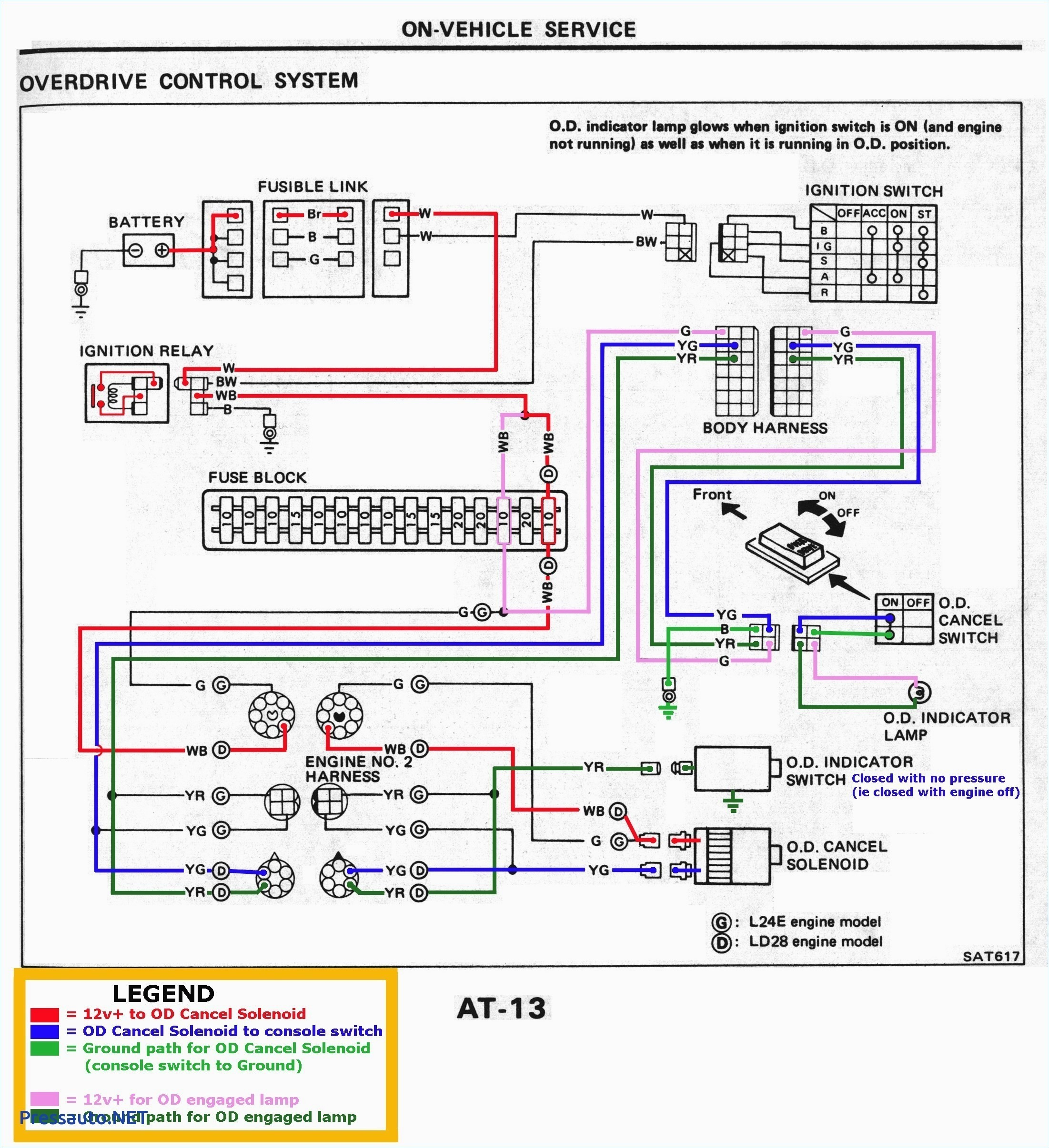
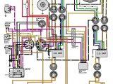
diagram johnson 115 hp outboard motor wiring diagram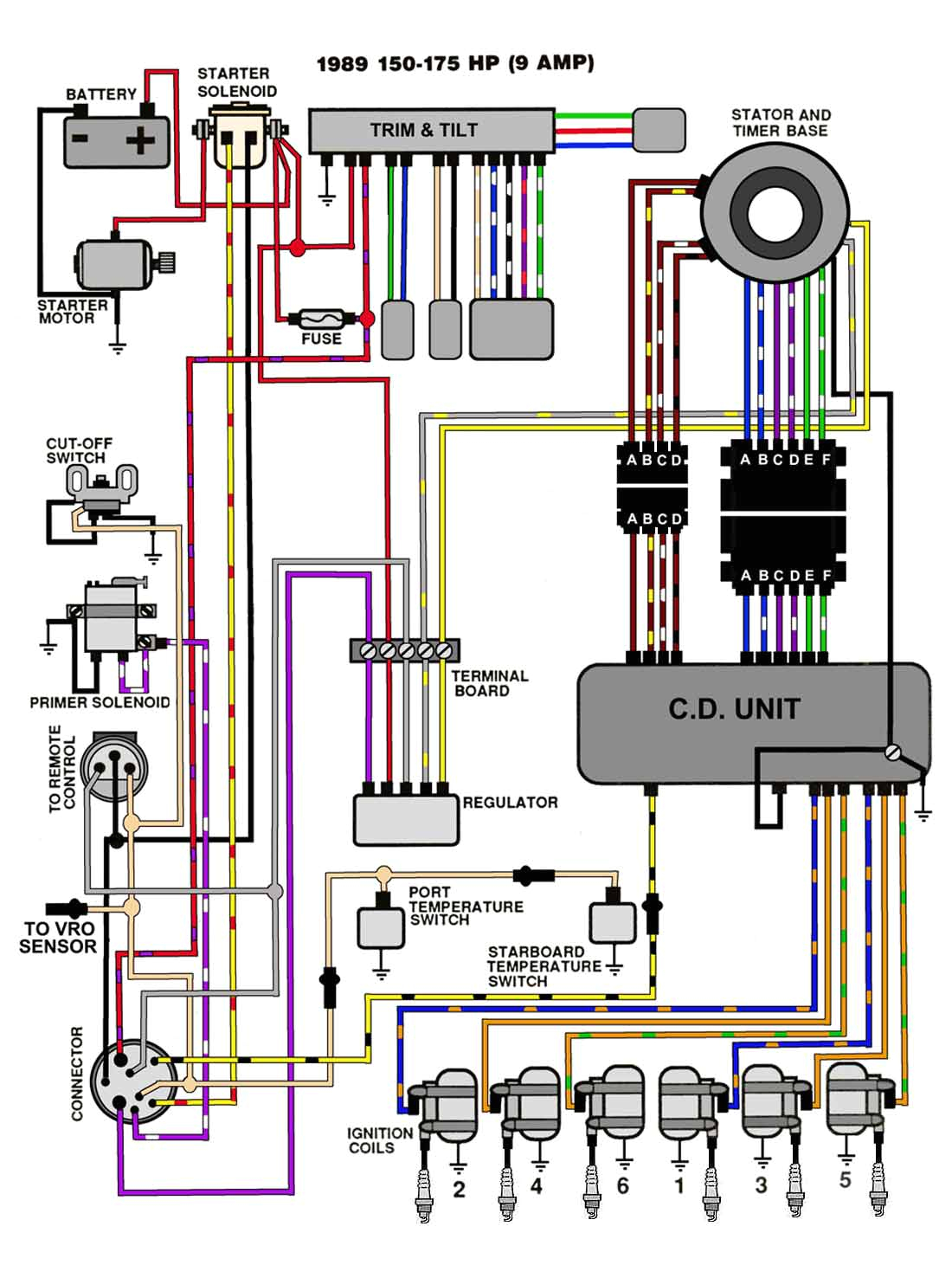
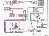
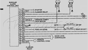
wiring schematic for johnson outboard
A set of wiring diagrams may be required by the electrical inspection authority to accept membership of the quarters to the public electrical supply system.
Wiring diagrams will in addition to put in panel schedules for circuit breaker panelboards, and riser diagrams for special facilities such as blaze alarm or closed circuit television or new special services.
You Might Also Like :
[gembloong_related_posts count=3]
johnson 115 outboard wiring diagram another image:
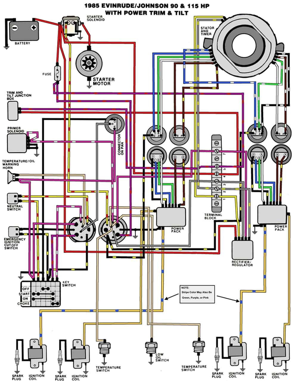
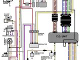
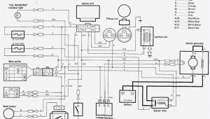
diagram johnson 115 hp wiring diagram full version hd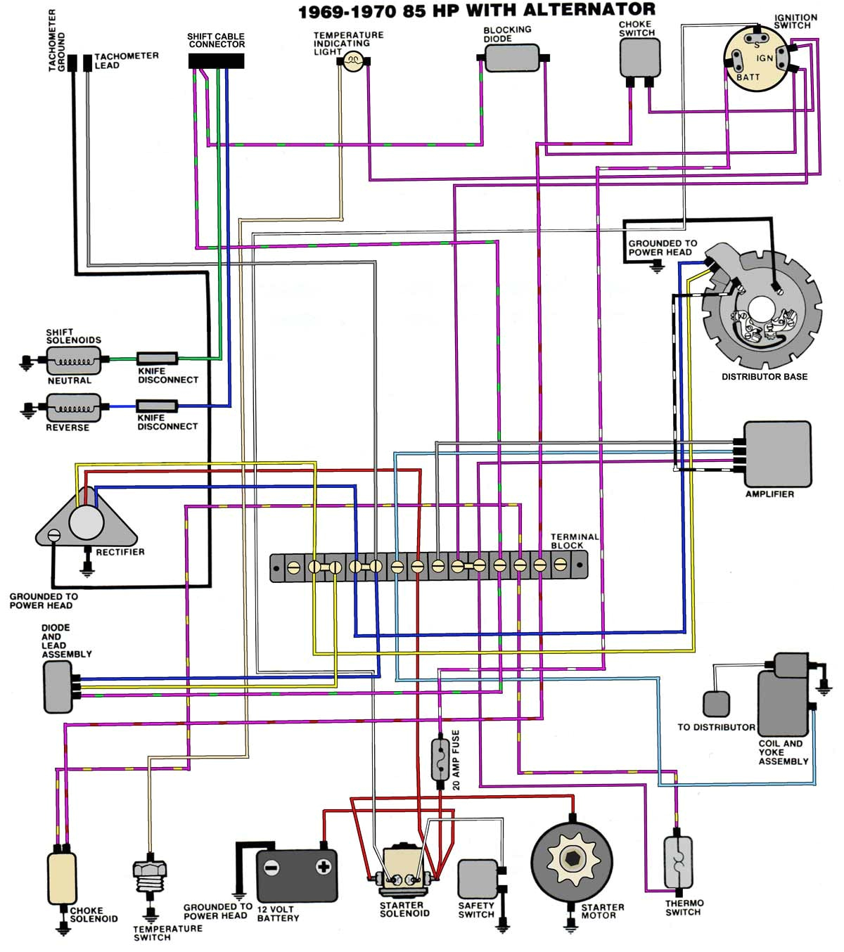
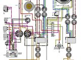
35 hp johnson outboard wiring diagram wiring diagram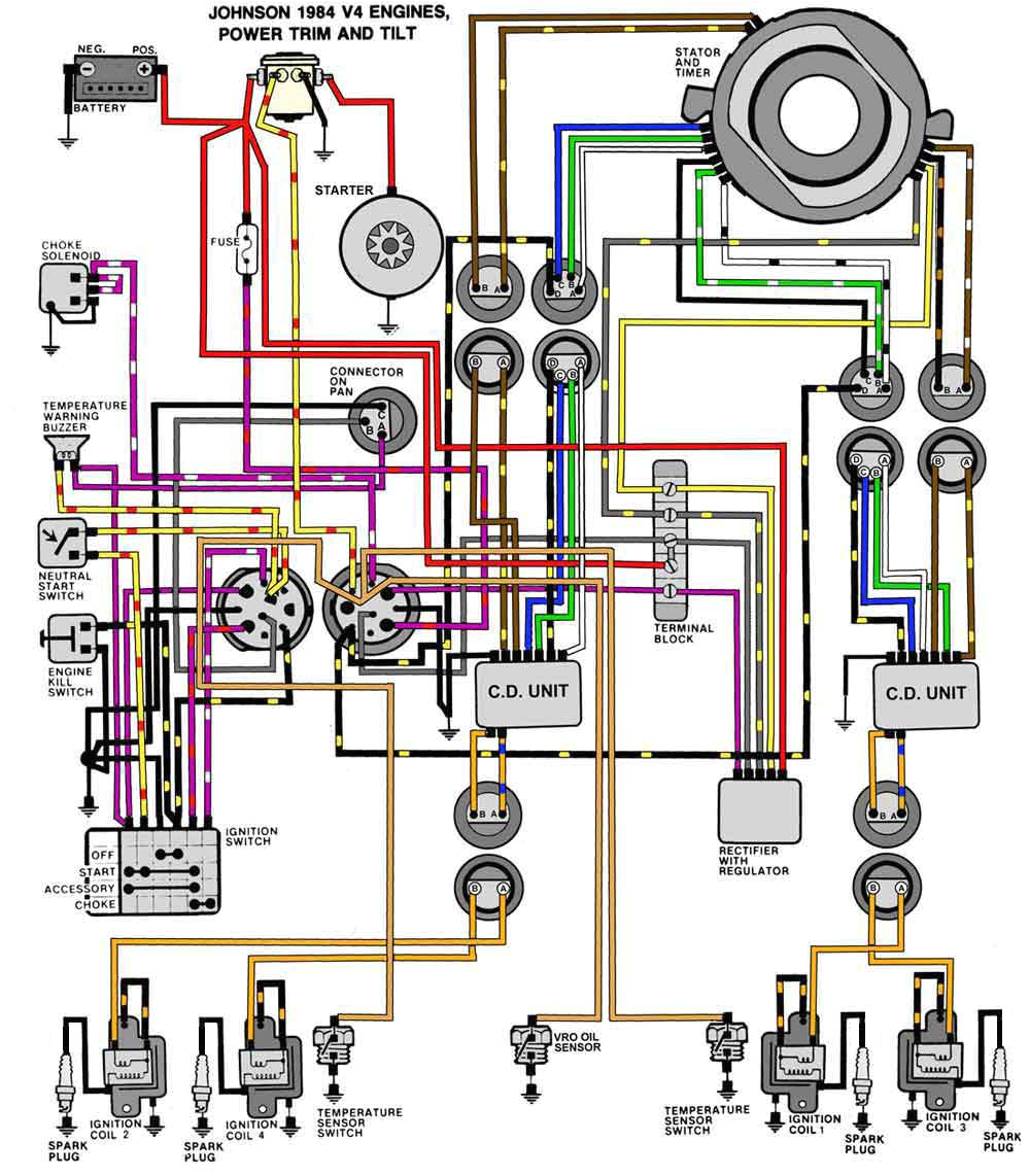
1998 johnson 115 manual
