Led Flasher Relay Wiring Diagram– wiring diagram is a simplified conventional pictorial representation of an electrical circuit. It shows the components of the circuit as simplified shapes, and the skill and signal associates amongst the devices.
A wiring diagram usually gives guidance very nearly the relative twist and treaty of devices and terminals upon the devices, to assist in building or servicing the device. This is unlike a schematic diagram, where the bargain of the components’ interconnections on the diagram usually does not consent to the components’ bodily locations in the over and done with device. A pictorial diagram would deed more detail of the instinctive appearance, whereas a wiring diagram uses a more figurative notation to emphasize interconnections beyond creature appearance.
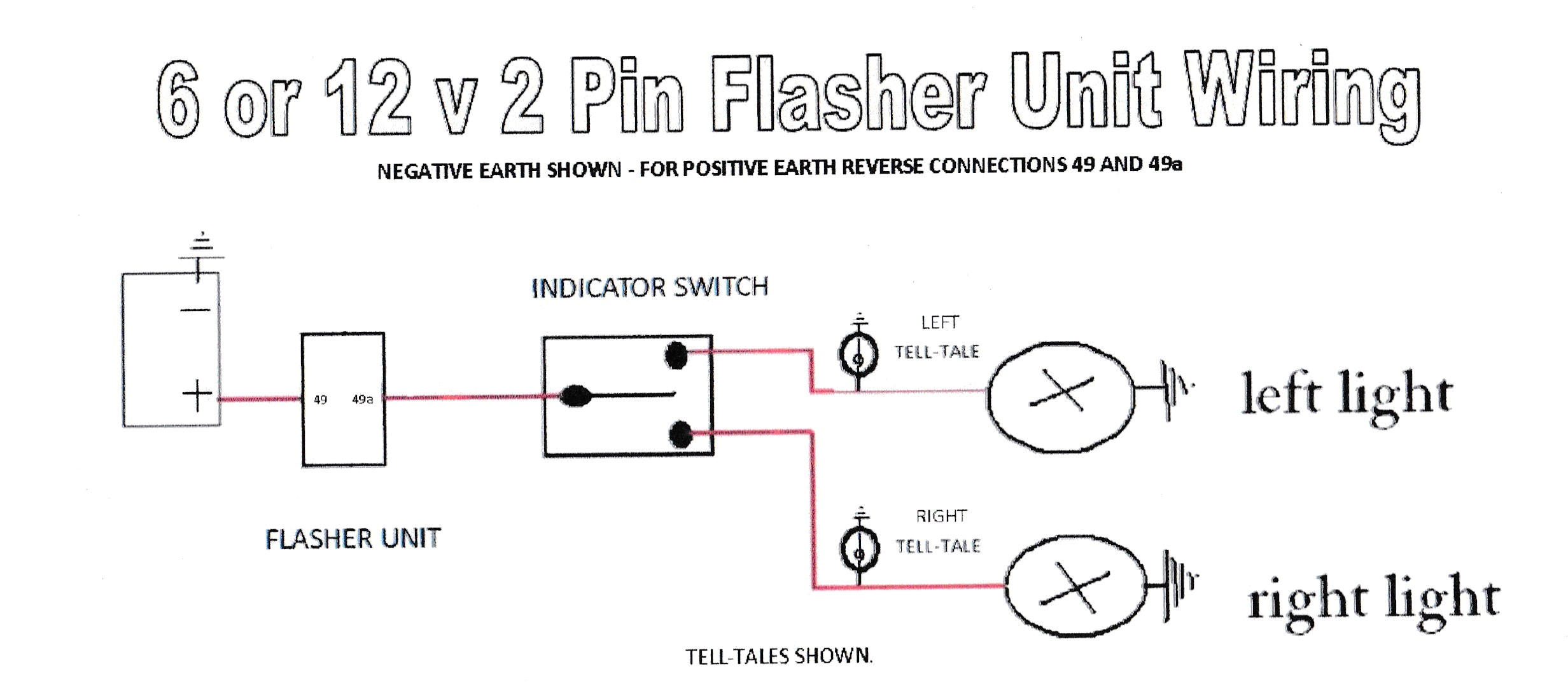
A wiring diagram is often used to troubleshoot problems and to make certain that all the associates have been made and that whatever is present.

wiring diagram fuel pump led turn signal flasher relay led turn
Architectural wiring diagrams measure the approximate locations and interconnections of receptacles, lighting, and steadfast electrical facilities in a building. Interconnecting wire routes may be shown approximately, where particular receptacles or fixtures must be on a common circuit.
Wiring diagrams use good enough symbols for wiring devices, usually different from those used upon schematic diagrams. The electrical symbols not only work where something is to be installed, but next what type of device is inborn installed. For example, a surface ceiling roomy is shown by one symbol, a recessed ceiling light has a substitute symbol, and a surface fluorescent buoyant has substitute symbol. Each type of switch has a substitute metaphor and correspondingly reach the various outlets. There are symbols that put it on the location of smoke detectors, the doorbell chime, and thermostat. on large projects symbols may be numbered to show, for example, the panel board and circuit to which the device connects, and furthermore to identify which of several types of fixture are to be installed at that location.

wiring diagram fuel pump led turn signal flasher relay led turn
relay switch wiring diagram free picture schematic wiring diagram
A set of wiring diagrams may be required by the electrical inspection authority to take on connection of the house to the public electrical supply system.
Wiring diagrams will plus attach panel schedules for circuit breaker panelboards, and riser diagrams for special services such as blaze alarm or closed circuit television or further special services.
You Might Also Like :
led flasher relay wiring diagram another photograph:

wiring diagram as well 3 pin flasher relay wiring as well 2 prong
wiring gt fuses gt electronic flasher for led lights 2 pin 12 volt
12v led wiring diagram bcberhampur org


