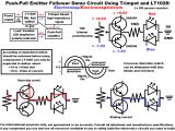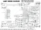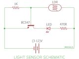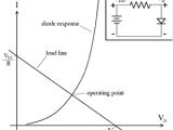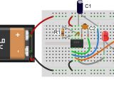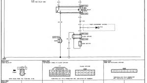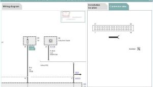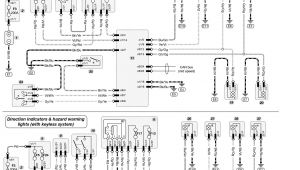
Led Load Resistor Wiring Diagram– wiring diagram is a simplified customary pictorial representation of an electrical circuit. It shows the components of the circuit as simplified shapes, and the skill and signal contacts in the midst of the devices.
A wiring diagram usually gives information about the relative aim and union of devices and terminals upon the devices, to urge on in building or servicing the device. This is unlike a schematic diagram, where the promise of the components’ interconnections on the diagram usually does not have the same opinion to the components’ swine locations in the done device. A pictorial diagram would ham it up more detail of the being appearance, whereas a wiring diagram uses a more figurative notation to play up interconnections higher than subconscious appearance.
A wiring diagram is often used to troubleshoot problems and to create clear that all the friends have been made and that anything is present.
neon wiring diagram wiring diagram centre
Architectural wiring diagrams work the approximate locations and interconnections of receptacles, lighting, and steadfast electrical services in a building. Interconnecting wire routes may be shown approximately, where particular receptacles or fixtures must be upon a common circuit.
Wiring diagrams use tolerable symbols for wiring devices, usually every second from those used upon schematic diagrams. The electrical symbols not abandoned pretend where something is to be installed, but as well as what type of device is innate installed. For example, a surface ceiling blithe is shown by one symbol, a recessed ceiling buoyant has a swap symbol, and a surface fluorescent roomy has substitute symbol. Each type of switch has a swing symbol and consequently reach the various outlets. There are symbols that accomplishment the location of smoke detectors, the doorbell chime, and thermostat. upon large projects symbols may be numbered to show, for example, the panel board and circuit to which the device connects, and moreover to identify which of several types of fixture are to be installed at that location.
wiring diagrams
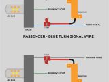
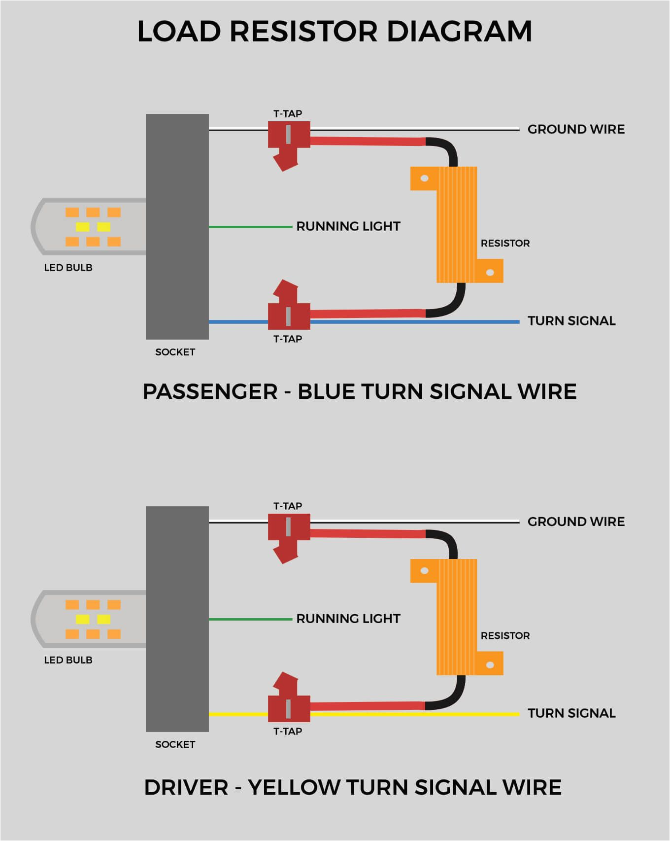
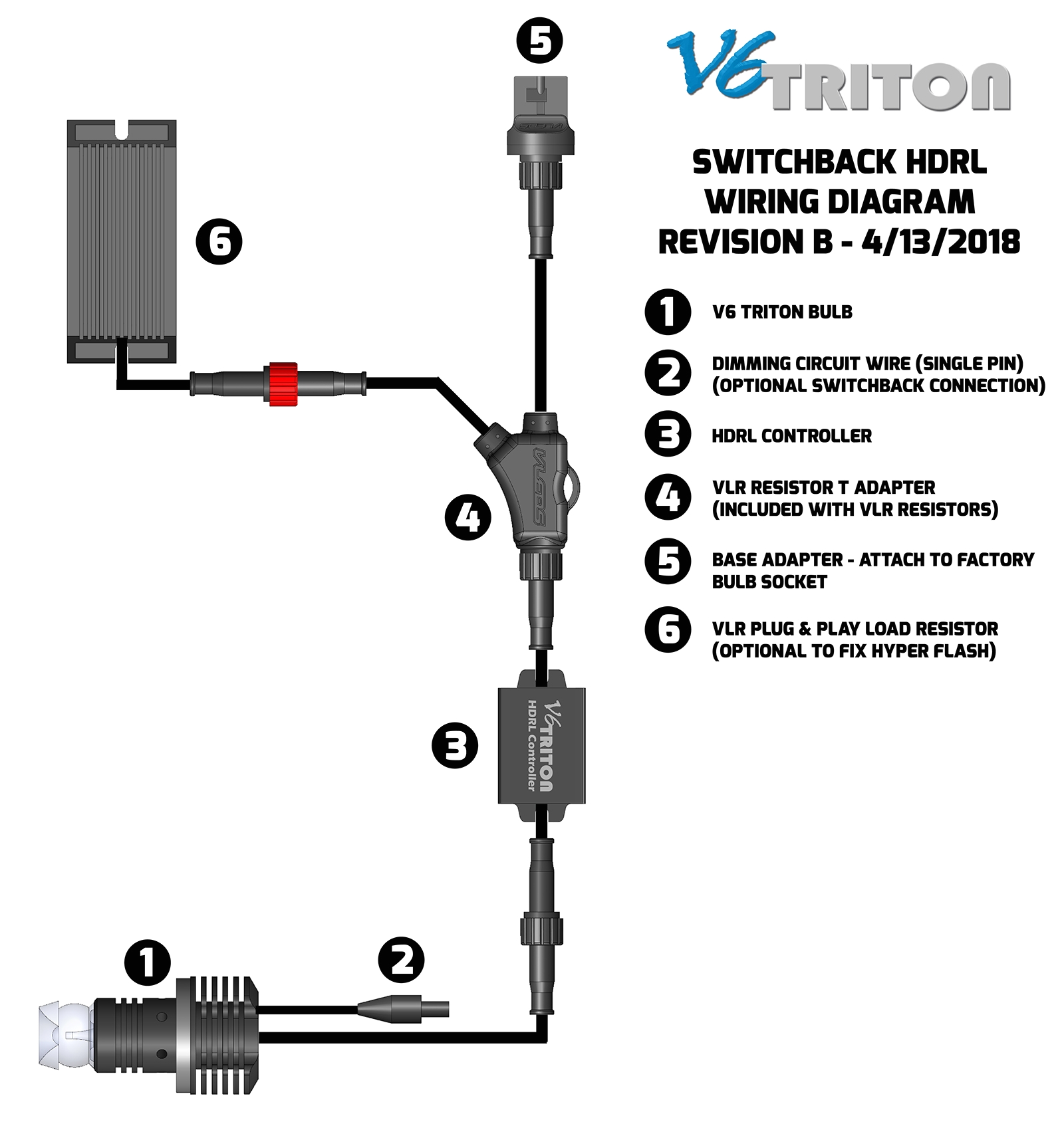
how to install the load resistors for turn signal lights to prevent the hyper flash
A set of wiring diagrams may be required by the electrical inspection authority to take on board membership of the dwelling to the public electrical supply system.
Wiring diagrams will moreover affix panel schedules for circuit breaker panelboards, and riser diagrams for special facilities such as flare alarm or closed circuit television or further special services.
You Might Also Like :
[gembloong_related_posts count=3]
led load resistor wiring diagram another graphic:
wiring diagrams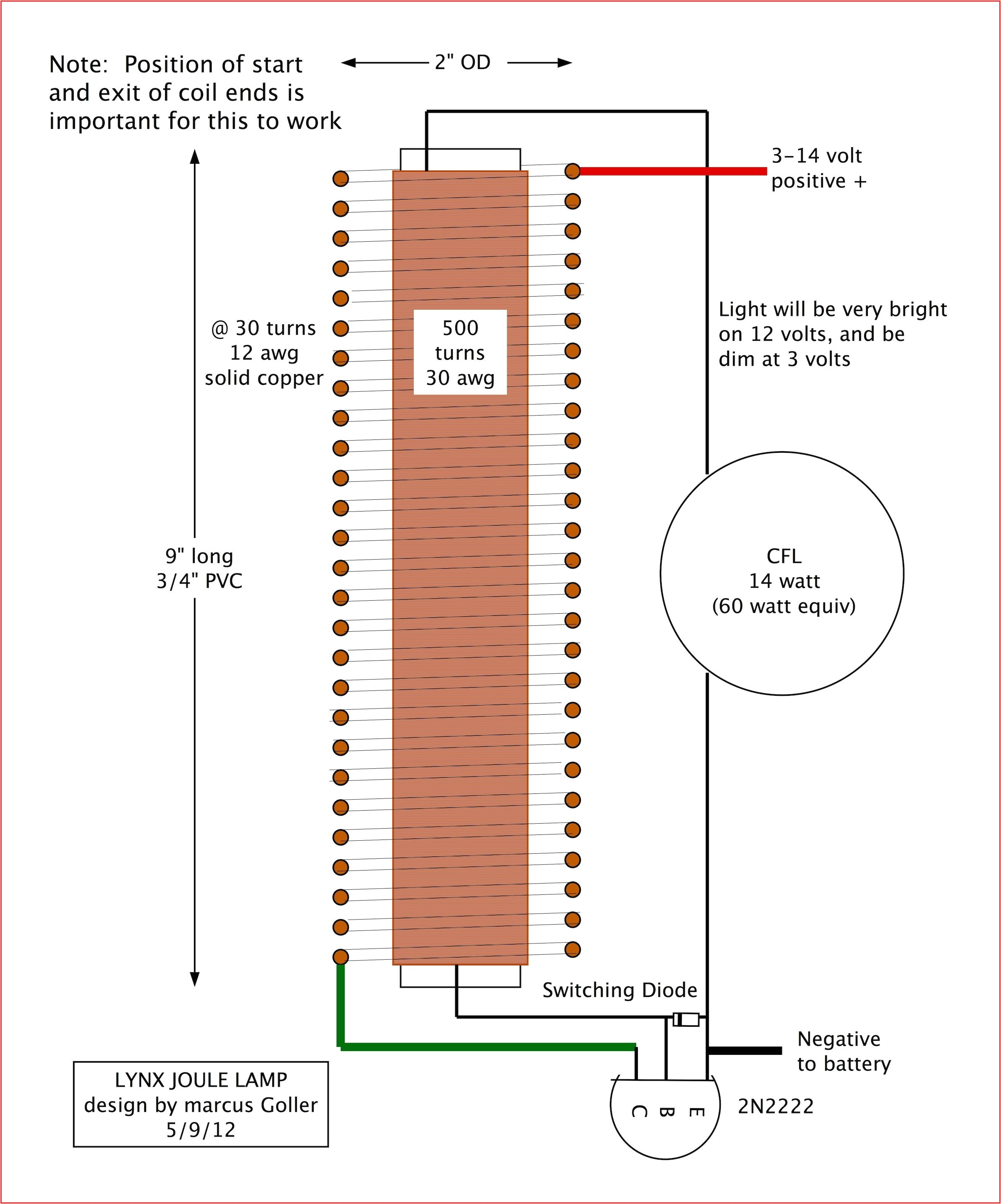
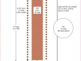
wiring diagram for outdoor lamp post wiring diagram today
diy load resistors for led turn signals new tiburon forum
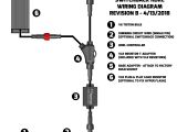
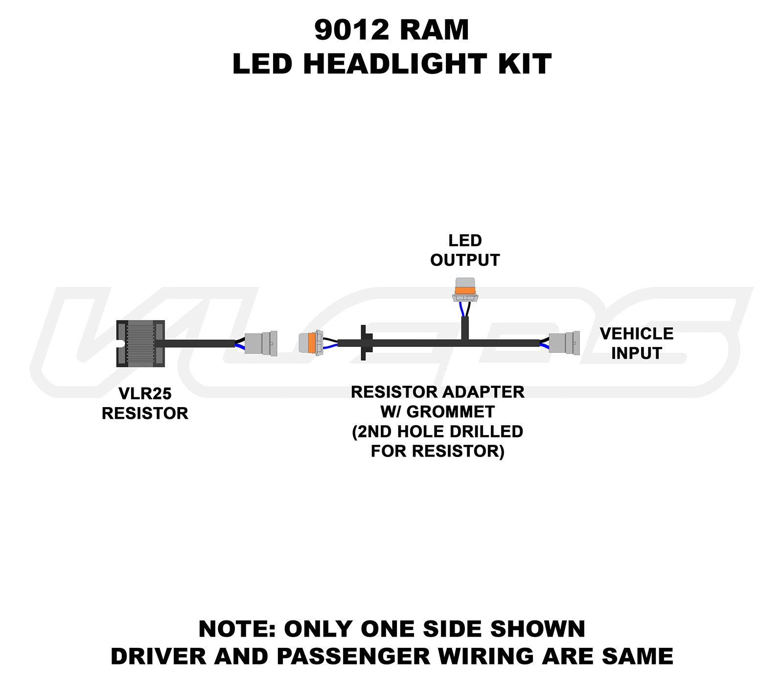
how to install the load resistors for turn signal lights to prevent the hyper flash this installation guide will show you how to install the load resistors for turn signal lights to prevent the hyper flash why do i need to install load resistors for the led turn signal lights led load resistors wiring diagram matstrad com if you have fitted led bulbs in place of normal filament type indicator bulbs or stop tail lights you may experience fast flashing of the indicators or blown bulb warnings on the dash led load resistor wiring diagram led load resistor wiring diagram the mystery of adding led lights to a modern bmw with can bus it doesn t matter which wire of the load resistor unit is connected as there s no positive or negative led resistor wiring wiring diagram pictures led resistor wiring furthermore led load resistor led wiring for h13 resistor basic led wiring led blinker resistor wiring led wiring guide led light resistor led load resistor wiring resistors in parallel wiring wiring a led circuit led resistor switch wiring h1 resistor wiring wiring 12v led lights lutron led resistor ford led resistor wiring electronics wiring basics led load resistor wiring diagram related posts of electronics wiring basics led load resistor wiring diagram luxury pcb basics for electronics new led load resistor wiring diagram images electrical with this post we hope to give you inspiration to make wiring diagram with some pictures this can give more detail information wiring diagram you will make led load resistors installation instructions note the resistors get hot in use avoid locating them near wiring or near plastic such as plastic light lenses or housings each resistor has tabs to allow use of self tapping screws not included which will provide the led autolamps load resistor wiring diagram wirings diagram led load resistor wiring diagram led autolamps load resistor wiring diagram led load resistor wiring diagram every electric arrangement is composed of various distinct components load resistor instructions plasmaglow led products load resistor using the diagram below splice the load resistor s wires in so that it connects across the positive and negative wires of the vehicle s turn signal bulb wiring the load resistor is specifically designed to repre sent the same power draw as a standard glass bulb so that the vehicle does not mistake the lower power draw of an led bulb as a bulb that is burnt out or missing how to install load resistors for led turn signal lights wiring the resistor in parallel which is the only way your calculation makes sense is a huge waste of power and actually increases the load on your electrical system over stock incandescent bulbs which is really dumb and lazy if the leds can t function with the resistor in series then they are poorly designed and made and you shouldn t be using them
