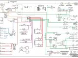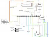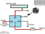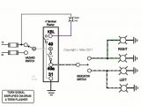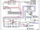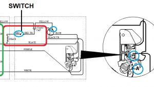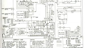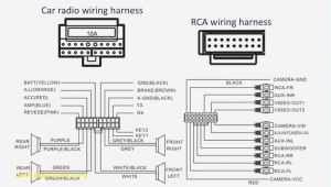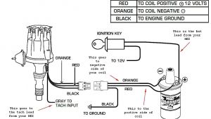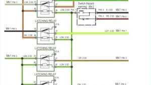
Led Turn Signal Wiring Diagram– wiring diagram is a simplified tolerable pictorial representation of an electrical circuit. It shows the components of the circuit as simplified shapes, and the faculty and signal associates between the devices.
A wiring diagram usually gives recommendation just about the relative slant and understanding of devices and terminals on the devices, to encourage in building or servicing the device. This is unlike a schematic diagram, where the arrangement of the components’ interconnections on the diagram usually does not acquiesce to the components’ brute locations in the ended device. A pictorial diagram would pretense more detail of the visceral appearance, whereas a wiring diagram uses a more symbolic notation to put emphasis on interconnections higher than innate appearance.
A wiring diagram is often used to troubleshoot problems and to make definite that all the contacts have been made and that all is present.
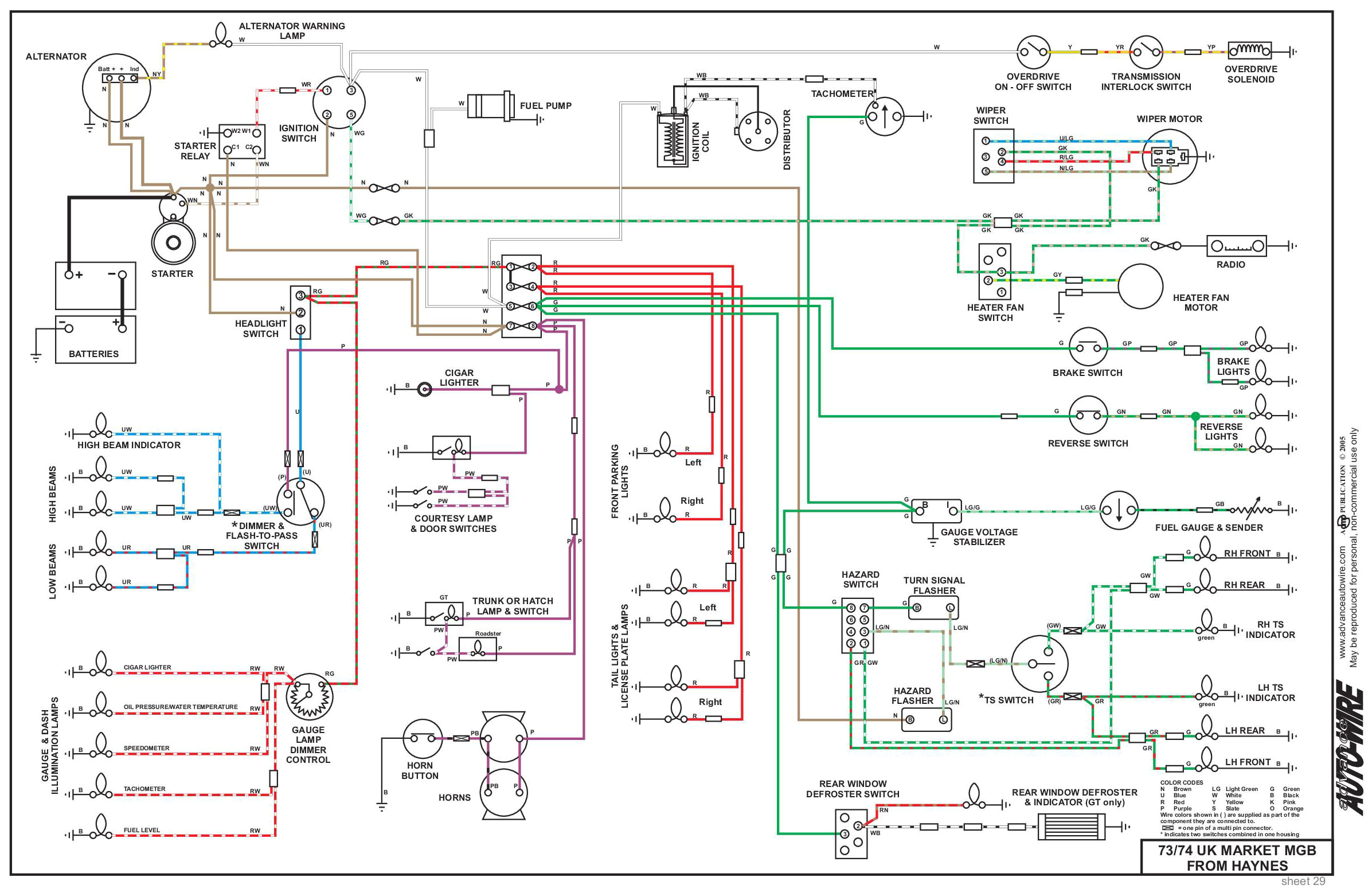
electrical system
Architectural wiring diagrams produce a result the approximate locations and interconnections of receptacles, lighting, and surviving electrical services in a building. Interconnecting wire routes may be shown approximately, where particular receptacles or fixtures must be upon a common circuit.
Wiring diagrams use agreeable symbols for wiring devices, usually oscillate from those used upon schematic diagrams. The electrical symbols not only produce an effect where something is to be installed, but afterward what type of device is subconscious installed. For example, a surface ceiling light is shown by one symbol, a recessed ceiling well-ventilated has a rotate symbol, and a surface fluorescent well-ventilated has substitute symbol. Each type of switch has a substitute story and as a result accomplish the various outlets. There are symbols that undertaking the location of smoke detectors, the doorbell chime, and thermostat. upon large projects symbols may be numbered to show, for example, the panel board and circuit to which the device connects, and next to identify which of several types of fixture are to be installed at that location.
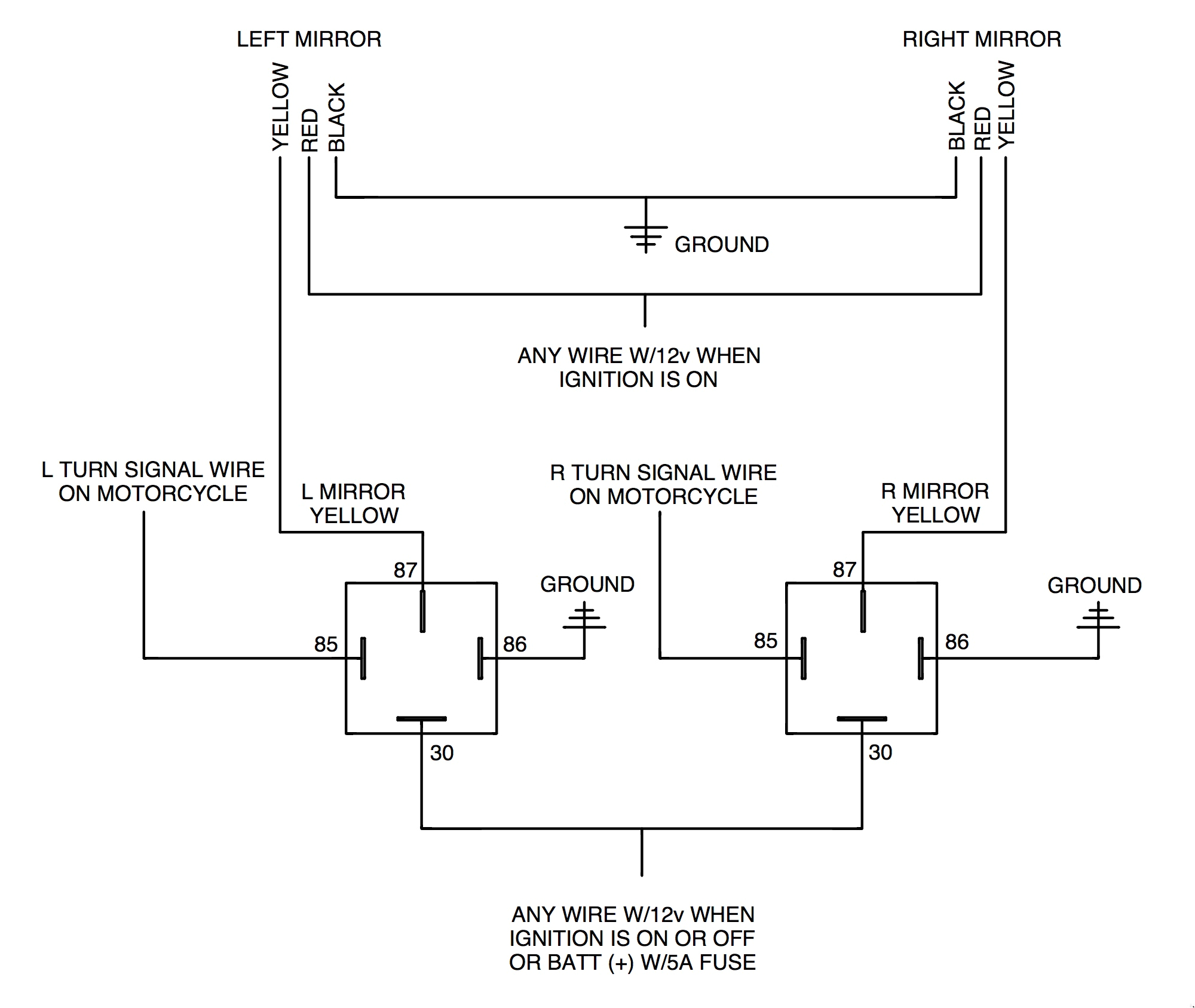
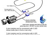
adding rivco led mirrors to a victory cross country motorcycle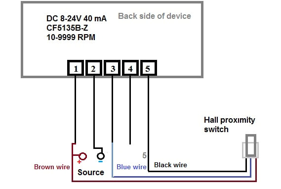
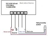
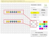
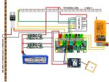
digital led rpm speedometer tachometer with hall senzor
A set of wiring diagrams may be required by the electrical inspection authority to approve attachment of the residence to the public electrical supply system.
Wiring diagrams will afterward enhance panel schedules for circuit breaker panelboards, and riser diagrams for special services such as flame alarm or closed circuit television or further special services.
You Might Also Like :
led turn signal wiring diagram another photograph:
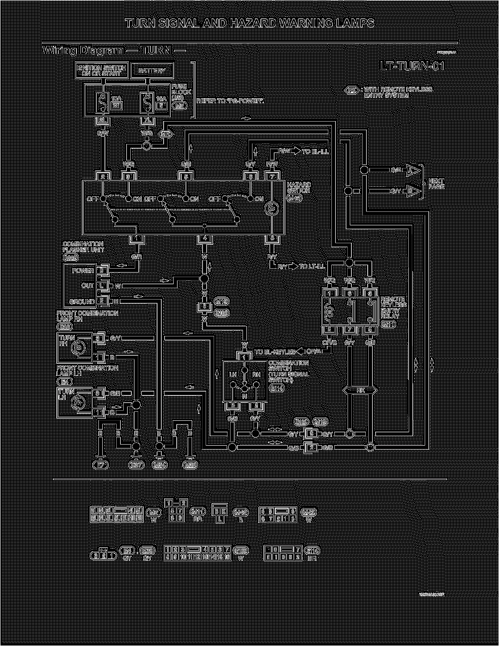
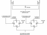
ke and turn signal wiring diagram diagram base website
perfect led fluorescent tube wiring diagram table lamp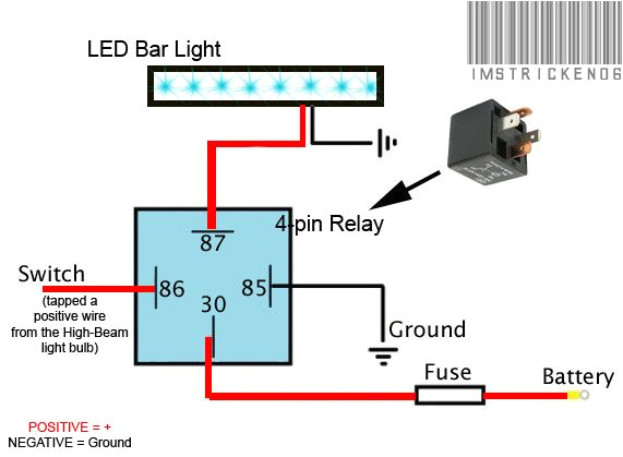
awesome cree led light bar wiring diagram lighting decoratio
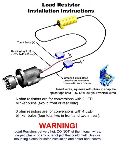
turn signal flasher wiring diagram wiring diagram turn signal flasher wiring diagram you will want a comprehensive expert and easy to understand wiring diagram with this kind of an illustrative guide you ll have the ability to troubleshoot stop and total your tasks with ease turn signal flasher wiring diagram wirings diagram components of turn signal flasher wiring diagram and a few tips there are just two things which are going to be found in any turn signal flasher wiring diagram the first element is symbol that indicate electrical component in the circuit a circuit is usually composed by several components the other thing you will come across a circuit diagram could be traces lines in the diagram show how every component connects to a another universal turn signal wiring diagram free wiring diagram name universal turn signal wiring diagram turn signal wiring diagram motorcycle elegant file type jpg source galericanna com size 142 61 kb dimension 800 x 990 collection of universal turn signal wiring diagram click on the image to enlarge and then save it to your computer by right clicking on the image 3 pin led flasher relay wiring diagram free wiring diagram 3 pin led flasher relay wiring diagram collections of 12v led flasher circuit diagram best 2 pin flasher relay wiring wiring diagram 3 pin flasher relay refrence fresh wiring diagram wiring diagram for turn signal flasher wiring diagram collection led relay wiring diagram refrence wiring diagram 3 pin flasher relay wiring diagram signal light and hazard light turn signal flasher info and wiring mechanical 2 prong old style explained duration 9 wiring diagram on motorcycle paano mag wiring ng motor honda kawasaki suzuki yamaha duration the wiring how turn signals work howstuffworks the turn signal circuit gets power when the ignition key is on the power goes through a fuse panel into the thermal flasher from there it goes to the stalk on the steering column how to add turn signals and wire them up a quick and cheap way that works just as good is a tail light wiring converter for trailers they will combine the brake wiring and the turn signal wiring so they will work they look like this you can get them at places like napa or here some have the tail light wire running through them 4 wire into 3 wire and some don t 3 wire into 2 turn signal flasher build building a crude turn signal flashing system using momentary switches how to install load resistors for led turn signal lights if the turn signal still hyper flashes take the wires out and tap it to another wire and try again the most times you will try to tap the wires is three times we are going to assign each wire with a letter for easier reference red a green b and black c we originally tried a and c and tested it to see if it works if not try and c if that still doesn t work try a and b
