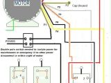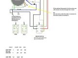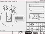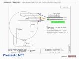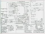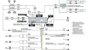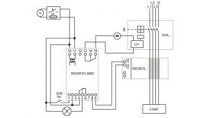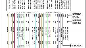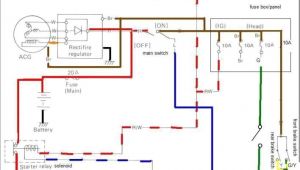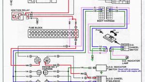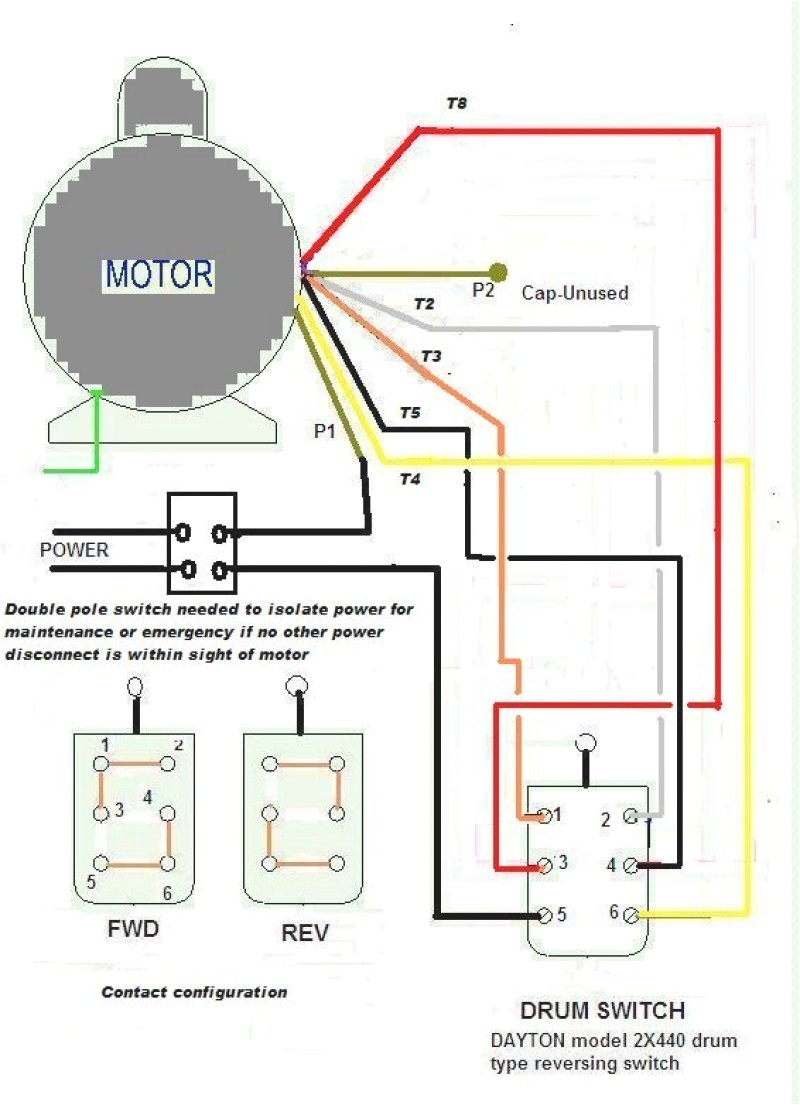
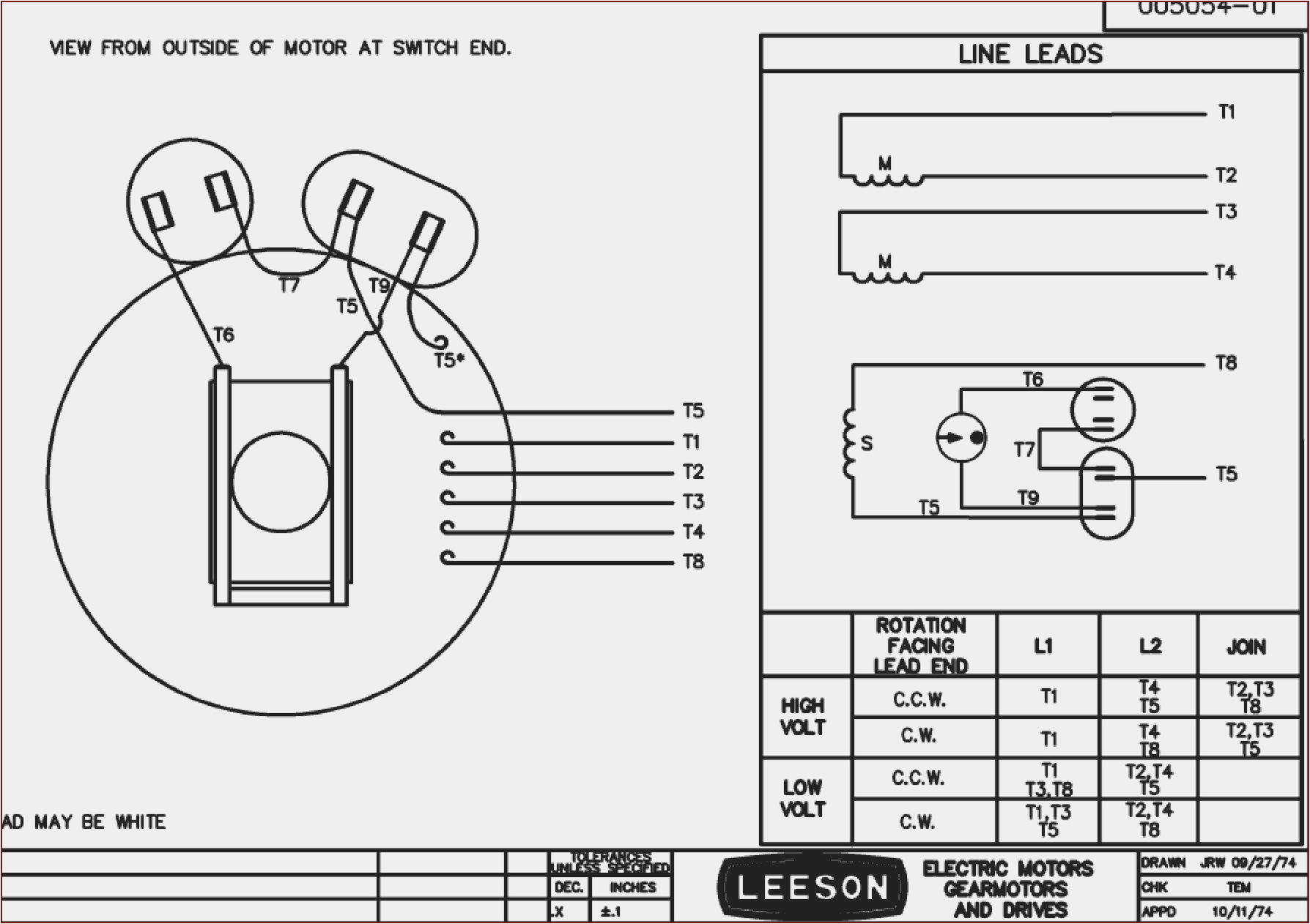
Leeson Electric Motors Wiring Diagrams– wiring diagram is a simplified good enough pictorial representation of an electrical circuit. It shows the components of the circuit as simplified shapes, and the capability and signal connections amongst the devices.
A wiring diagram usually gives recommendation approximately the relative tilt and contract of devices and terminals upon the devices, to help in building or servicing the device. This is unlike a schematic diagram, where the settlement of the components’ interconnections upon the diagram usually does not accede to the components’ instinctive locations in the curtains device. A pictorial diagram would affect more detail of the physical appearance, whereas a wiring diagram uses a more figurative notation to emphasize interconnections on top of swine appearance.
A wiring diagram is often used to troubleshoot problems and to create positive that all the contacts have been made and that all is present.
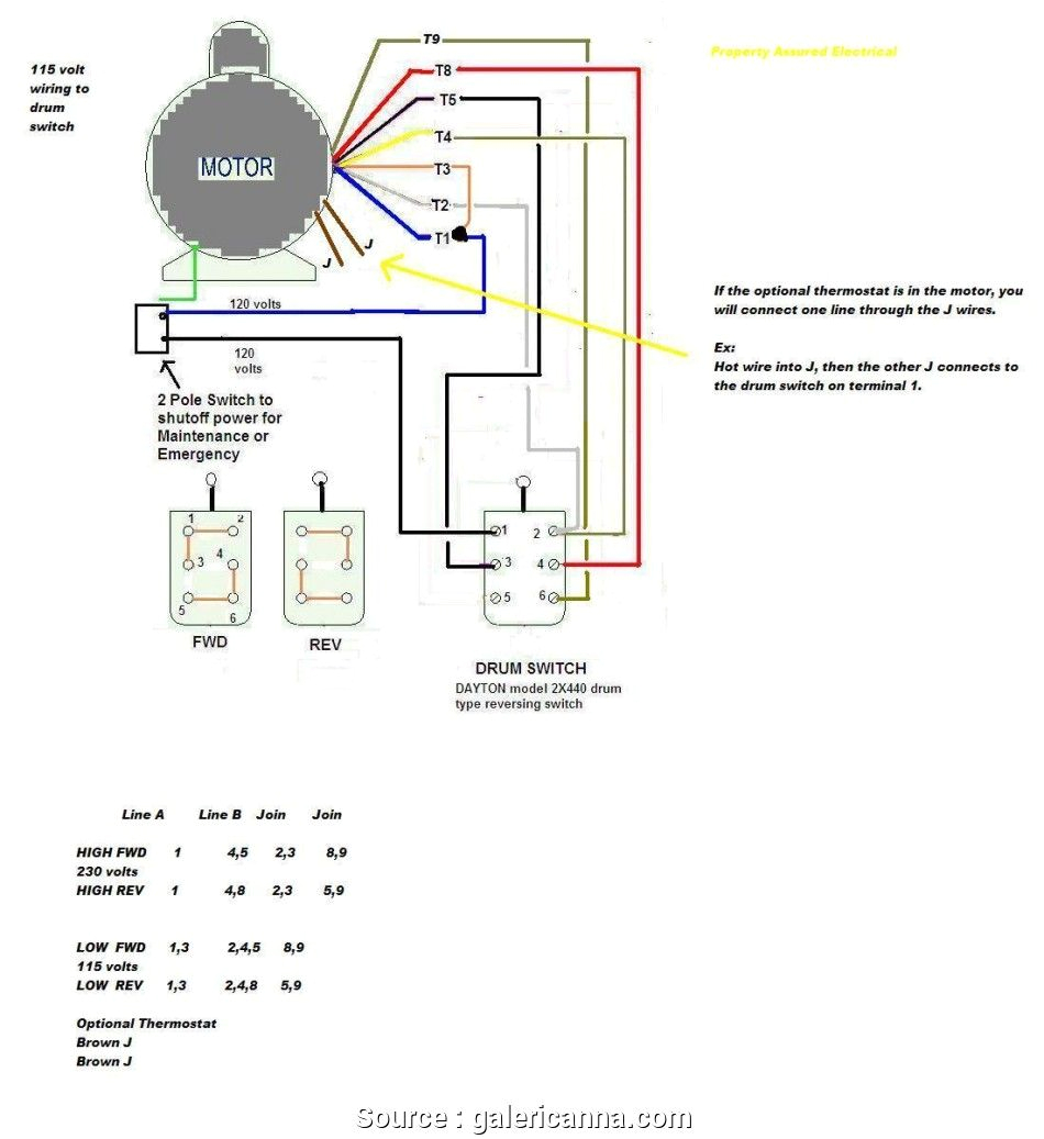
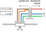
a single phase delta motor wiring wiring diagram
Architectural wiring diagrams act out the approximate locations and interconnections of receptacles, lighting, and remaining electrical services in a building. Interconnecting wire routes may be shown approximately, where particular receptacles or fixtures must be on a common circuit.
Wiring diagrams use within acceptable limits symbols for wiring devices, usually alternative from those used on schematic diagrams. The electrical symbols not unaided fake where something is to be installed, but plus what type of device is monster installed. For example, a surface ceiling fresh is shown by one symbol, a recessed ceiling roomy has a substitute symbol, and a surface fluorescent fresh has another symbol. Each type of switch has a alternating metaphor and correspondingly get the various outlets. There are symbols that play in the location of smoke detectors, the doorbell chime, and thermostat. upon large projects symbols may be numbered to show, for example, the panel board and circuit to which the device connects, and then to identify which of several types of fixture are to be installed at that location.
mars fan motor wiring diagram at manuals library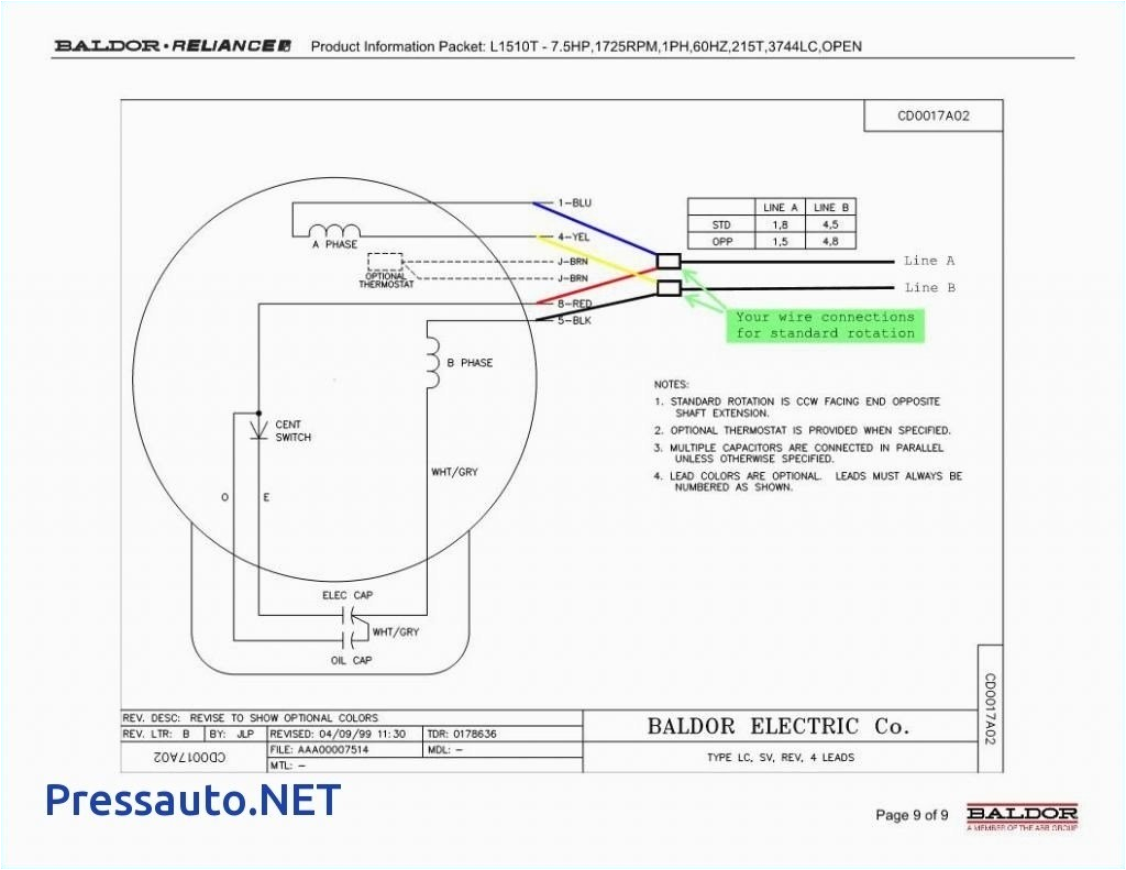
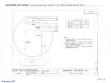
baldor electric motor wiring diagram anvelopesecondhand net
A set of wiring diagrams may be required by the electrical inspection authority to approve connection of the quarters to the public electrical supply system.
Wiring diagrams will moreover enlarge panel schedules for circuit breaker panelboards, and riser diagrams for special facilities such as flame alarm or closed circuit television or supplementary special services.
You Might Also Like :
- Hammond Power solutions Wiring Diagram
- 2013 Tacoma Wiring Diagram
- Aftermarket Radio Wiring Harness Diagram
leeson electric motors wiring diagrams another image:
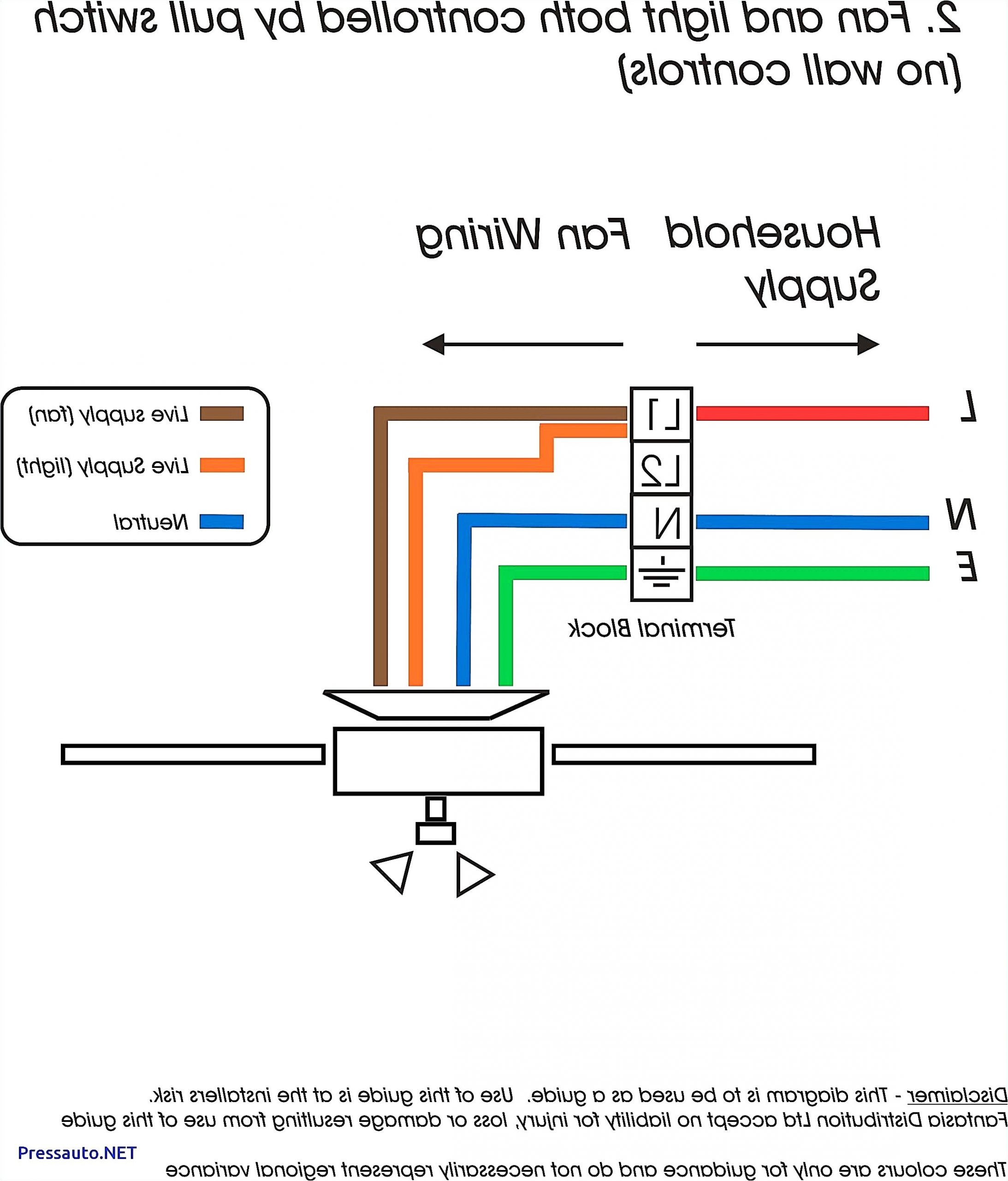
weg single phase wiring diagram wiring diagram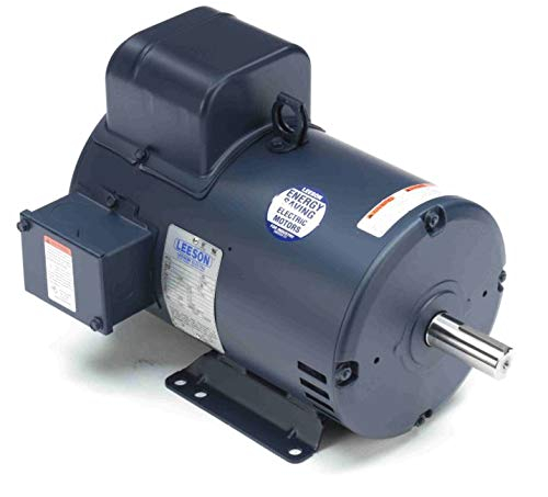
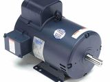
7 5hp 3450rpm 184t frame 208 230 volts open drip leeson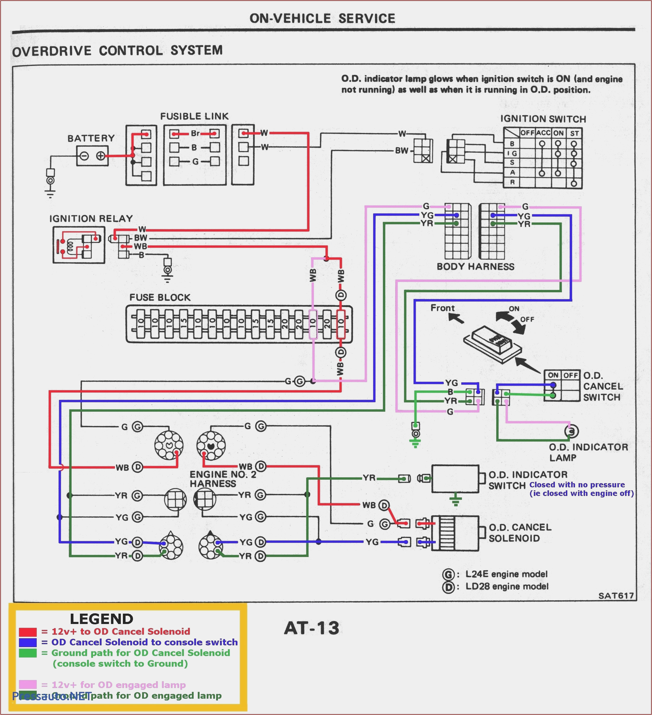
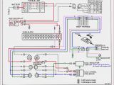
general motors wiring diagrams at manuals library
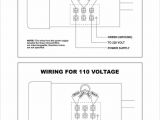
leeson electric motor wiring diagram free wiring diagram leeson electric motor wiring diagram collections of dorable leeson electric motor wiring diagram vignette electrical amazing baldor electric motor wiring diagram motors 10 3 wiring wiring diagram leeson electric motor refrence wiring diagram for ac dayton hoist wiring diagram best wiring diagram for dayton leeson electric motor wiring diagram wirings diagram leeson electric motor wiring diagram leeson ac gear motor wiring diagram leeson ac motor wiring diagram leeson electric motor wiring diagram every electric arrangement is made up of various diverse components each part ought to be set and linked to different parts in specific manner if not the arrangement will not work as it should be in order to be certain the electrical circuit is leeson motor wiring diagram free wiring diagram leeson motor wiring diagram collections of leeson motor wiring schematic gallery 1 hp electric motor wiring diagram wire center electric motor wiring for 110 volts century electric motors dayton hoist wiring diagram best wiring diagram for dayton leeson motor wiring diagram wiring diagram and schematic leeson motor wiring diagram here you are at our website today we are excited to announce we have discovered an awfully interesting content to be pointed out that is leeson motor wiring diagram many people trying to find specifics of leeson motor wiring diagram and of course one of these is you is not it leeson electric motor wiring diagram best free wiring leeson electric motor wiring diagram welcome to our site this is images about leeson electric motor wiring diagram posted by benson fannie in leeson category on nov 01 2019 you can also find other images like images wiring diagram images parts diagram images replacement parts images electrical diagram images repair manuals images engine leeson single phase motor wiring diagrams engine diagram this is a image galleries about leeson single phase motor wiring diagrams you can also find other images like wiring diagram parts diagram replacement parts electrical diagram repair manuals engine diagram engine scheme wiring harness fuse box vacuum diagram timing belt timing chain brakes diagram transmission diagram and engine leeson 1hp motor wiring diagram diagram visit the post for more leeson 1hp motor only leeson 1hp motor wiring diagram the best harness for auto restoration complete to tail lights speedmaster leeson single phase motor wiring diagram inspirational boat lift free engine great wiring diagram for baldor electric motor leeson sc 1 st blogdelaweb com within leeson electric motor wiring diagram and 128897d1422676808 from the thousand pictures on the net about leeson motor wiring diagram we all picks the very best series with ideal image resolution just for you and now this images is usually one of photographs series in this finest photos gallery with regards to leeson motor wiring diagram single phase motor wiring diagrams north american electric single phase motor wiring diagrams single voltage motor 208 230v ccw cw l2 l1 t1 t8 t4 t5 t1 t5 t4 t8 dual voltage motor 115v or 208 230v 208 230v or 460v low voltage high voltage ccw cw ccw cw l2 t1 t3 t8 t2 t4 t5 t1 t3 t5 t2 t4 t8 l1 t1 t3 t8 t2 t4 t5 t1 t3 t5 t2 t4 t8 l1 l2 dual voltage motor with manual overload mo 115v or 208 230v 208 electric motor wiring diagram describes with detailed information how to test automotive electric motors fuel pump analysis cooling fans etc when diagnosing a faulty automotive motor it is often impossible not to perform
